ALLPCB


Designing high-speed printed circuit boards (PCBs) requires precise control over impedance to ensure signal integrity and minimize data loss. One of the most critical factors in achieving this is selecting the right stackup materials. If you're wondering how to choose materials for impedance control in high-speed PCBs, this guide is for you. We'll dive deep into the role of PCB material dielectric constant, compare options like FR4 for impedance control and Rogers material for high-frequency applications, and explore low loss PCB materials to help you make informed decisions.
In this comprehensive blog, we'll break down the essentials of stackup materials, explain their impact on controlled impedance, and provide actionable insights for engineers and designers working on high-speed circuits. Whether you're tackling RF designs, 5G applications, or other high-frequency projects, you'll find the information you need to optimize your PCB performance.
What Is Impedance Control and Why Does It Matter in High-Speed PCBs?
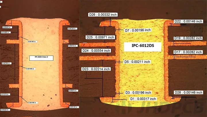
Impedance control in PCBs refers to the management of the electrical impedance of transmission lines on the board to match the source and load. When impedance is mismatched, signals can reflect back, causing noise, data errors, or signal degradation. In high-speed designs, where signals switch at gigahertz frequencies, even small mismatches can lead to significant issues.
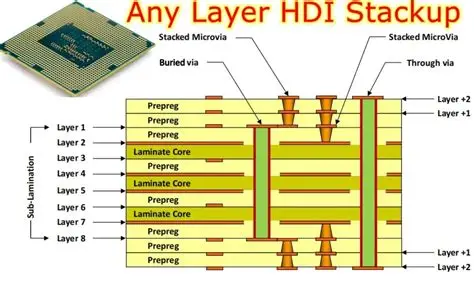
The stackup—the arrangement of conductive and insulating layers in a PCB—plays a vital role in determining impedance. The materials used in these layers, especially their dielectric constant (Dk) and dissipation factor (Df), directly affect how signals propagate through the board. Choosing the right materials ensures consistent impedance, reduces signal loss, and maintains performance in high-frequency environments.
Key Factors in Impedance Control
- Dielectric Constant (Dk): This measures a material’s ability to store electrical energy in an electric field. A lower Dk often means faster signal propagation, which is critical for high-speed designs.
- Dissipation Factor (Df): This indicates how much signal energy is lost as heat. Low Df materials are essential for minimizing signal loss in high-frequency applications.
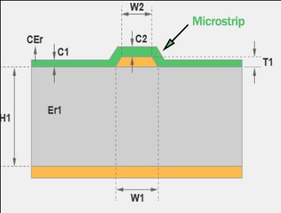
- Trace Geometry: The width and thickness of traces, along with their spacing, interact with the material properties to set impedance values (e.g., 50 ohms for many RF designs).
- Layer Thickness: The distance between conductive layers and ground planes affects impedance and must be carefully planned in the stackup design.
Understanding PCB Material Dielectric Constant and Its Role in Impedance Control
The dielectric constant (Dk) of a PCB material is a measure of how much it slows down an electrical signal compared to a vacuum. Materials with a high Dk slow signals more, while those with a low Dk allow faster signal travel. For high-speed PCBs, a stable and predictable Dk is crucial for maintaining controlled impedance across frequencies.
For example, in a typical high-speed design targeting a 50-ohm impedance, the Dk of the material will influence the trace width and spacing needed. If the Dk varies with frequency or temperature (a common issue with some materials), the impedance can shift, leading to signal integrity problems.
Common Dk values for PCB materials range from about 2.2 to 4.5. Lower Dk materials are often preferred for high-frequency applications because they reduce signal delay and crosstalk. However, the choice of material also depends on cost, thermal performance, and manufacturing constraints.
FR4 for Impedance Control: Pros, Cons, and Applications
FR4 is the most widely used PCB material due to its affordability and versatility. It’s a composite of woven fiberglass and epoxy resin, offering decent mechanical strength and thermal stability. But how does FR4 perform when it comes to impedance control in high-speed designs?
Advantages of FR4 for Impedance Control
- Cost-Effective: FR4 is significantly cheaper than specialized high-frequency materials, making it ideal for budget-conscious projects.
- Stable Dielectric Constant: Standard FR4 has a Dk of around 4.2 to 4.5 at 1 MHz, which is reasonably consistent for many applications up to a few gigahertz.
- Wide Availability: FR4 is a standard material in the industry, supported by most fabrication processes.
Limitations of FR4 in High-Speed Designs
- Signal Loss at High Frequencies: FR4 has a higher dissipation factor (Df around 0.02), leading to greater signal loss above 5-6 GHz. For instance, signal loss can be around 0.5 dB higher per inch compared to advanced materials at these frequencies.
- Dielectric Constant Variation: The Dk of FR4 can vary with frequency and temperature, affecting impedance stability in demanding applications.
- Not Ideal for RF: For frequencies above 10 GHz, FR4 struggles to maintain signal integrity, making it unsuitable for cutting-edge RF or 5G designs.
When to Use FR4 for Impedance Control
FR4 is a great choice for high-speed designs operating below 5 GHz, such as in consumer electronics, industrial controls, and some networking equipment. With careful stackup design and simulation, FR4 can achieve controlled impedance (e.g., 50 ohms or 100 ohms differential) for these applications. However, for higher frequencies, you may need to consider alternatives.
Rogers Material for High-Frequency Applications: A Superior Choice
For high-frequency and RF designs, materials from a well-known manufacturer of advanced laminates stand out. These materials are engineered for low signal loss and stable performance, making them a top pick for applications like 5G, aerospace, and microwave circuits.
Benefits of High-Frequency Laminates
- Low Dielectric Constant: These materials offer Dk values as low as 2.2 to 3.5, enabling faster signal speeds and reduced crosstalk.
- Low Dissipation Factor: With Df values as low as 0.0009, they minimize signal loss, even at frequencies exceeding 10 GHz.
- High Thermal Stability: Many of these laminates have a glass transition temperature (Tg) above 280°C, far surpassing standard FR4 (135-180°C), ensuring reliability in harsh conditions.
- Consistent Performance: Their dielectric properties remain stable across a wide range of frequencies and temperatures, critical for precise impedance control.
Drawbacks to Consider
- Higher Cost: These advanced materials can be significantly more expensive than FR4, sometimes costing 5-10 times more per square foot.
- Manufacturing Complexity: They may require specialized fabrication processes, increasing lead times and costs.
Applications of High-Frequency Materials
These materials shine in applications requiring ultra-high frequencies, such as satellite communications, radar systems, and 5G infrastructure. For example, in a 28 GHz 5G antenna design, using a material with a Dk of 3.0 and Df of 0.001 can reduce signal loss by over 30% compared to FR4, ensuring reliable data transmission.
Low Loss PCB Materials: Beyond FR4 and High-Frequency Options
Besides FR4 and specialized high-frequency laminates, other low loss PCB materials are worth considering for impedance control in high-speed designs. These materials strike a balance between performance and cost, catering to specific needs.
Examples of Low Loss Materials
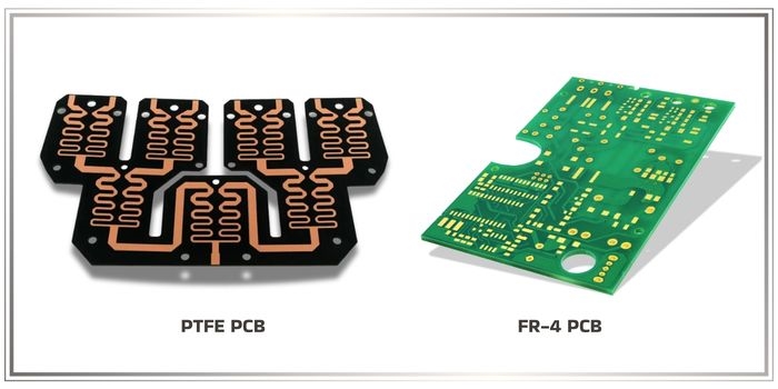
- PTFE-Based Materials: Polytetrafluoroethylene (PTFE) laminates offer a very low Dk (around 2.1) and Df (0.0002), ideal for microwave and RF circuits. They are often reinforced with ceramics or glass for added strength.
- Polyimide: Known for flexibility and thermal resistance, polyimide materials have a Dk of about 3.5 and are used in flexible PCBs for high-speed applications.
- Modified Epoxy Resins: Some enhanced epoxy materials provide lower loss than standard FR4 (Df around 0.01) while remaining cost-effective for mid-range frequencies.
Choosing the Right Low Loss Material
The choice depends on your design’s frequency range, thermal requirements, and budget. For instance, PTFE-based materials are excellent for frequencies above 20 GHz but can be brittle and costly. Polyimide, on the other hand, suits flexible designs with moderate frequency demands.
Controlled Impedance PCB Materials Comparison: Making the Right Choice
Selecting the best material for controlled impedance involves weighing multiple factors. Below is a comparison of key materials based on dielectric properties, frequency range, cost, and application suitability.
| Material | Dielectric Constant (Dk) | Dissipation Factor (Df) | Frequency Range | Cost | Typical Applications |
|---|---|---|---|---|---|
| Standard FR4 | 4.2-4.5 | 0.02 | Up to 5-6 GHz | Low | Consumer electronics, industrial controls |
| High-Frequency Laminate | 2.2-3.5 | 0.0009-0.003 | Up to 50+ GHz | High | 5G, RF, aerospace |
| PTFE-Based | 2.1-2.5 | 0.0002-0.001 | Up to 100 GHz | Very High | Microwave, satellite |
| Polyimide | 3.4-3.5 | 0.008-0.01 | Up to 10 GHz | Moderate | Flexible PCBs, high-speed connectors |
Hybrid Stackups: Combining Materials for Cost and Performance
In some cases, using a single material across all layers isn’t practical. Hybrid stackups combine different materials, such as pairing FR4 with a high-frequency laminate. For example, critical signal layers can use a low loss material for better performance, while less demanding layers use FR4 to save cost. This approach requires careful planning to ensure impedance continuity and manufacturability.
Practical Tips for Designing Stackups with Impedance Control
Choosing the right material is just the first step. Here are some actionable tips to optimize your PCB stackup for controlled impedance:
- Use Simulation Tools: Software can predict impedance based on material properties, trace geometry, and layer thickness. Aim for precise values like 50 ohms or 100 ohms differential.
- Minimize Layer Transitions: Route high-speed signals on a single layer when possible to avoid impedance discontinuities.
- Work with Fabricators Early: Material availability and manufacturing tolerances can affect stackup design. Collaborate with your fabrication partner to finalize Dk values and layer thicknesses.
- Account for Frequency Range: Select a material whose dielectric properties remain stable across your operating frequency. For instance, a Dk variation of just 0.1 can shift impedance by several ohms at 10 GHz.
- Consider Thermal Expansion: Materials with mismatched coefficients of thermal expansion (CTE) can cause reliability issues in multilayer designs. Match CTE values as closely as possible.
Conclusion: Building High-Speed PCBs with the Right Stackup Materials
Achieving impedance control in high-speed PCBs starts with understanding the properties of stackup materials. From the widely used FR4 for impedance control in moderate frequencies to advanced Rogers material for high-frequency applications, each option has its strengths and trade-offs. By considering factors like PCB material dielectric constant, dissipation factor, and frequency requirements, you can select the best material—or combination of materials—for your design.
Whether you're working on a cost-sensitive project with FR4 or pushing the limits of 5G with low loss PCB materials, this guide offers a foundation for success. Use the controlled impedance PCB materials comparison to weigh your options, and follow practical design tips to ensure signal integrity. With the right stackup, your high-speed PCB will deliver reliable performance, even in the most demanding applications.
At ALLPCB, we’re committed to supporting your design journey with high-quality materials and fabrication expertise. Explore our resources and services to bring your high-speed PCB projects to life.