Overview
The power system consists of generation, transmission, substation, distribution, and user-side equipment, together with their auxiliary systems.
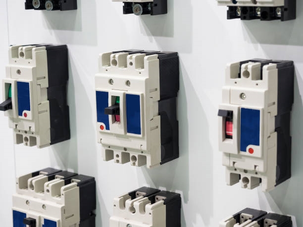
Electrical equipment in power plants and substations is divided into primary equipment and secondary equipment. Primary equipment (also called main equipment) forms the core of the power system and is directly responsible for generating, transmitting, and distributing electric power. Examples include generators, transformers, switching devices, power lines, instrument transformers, and surge arresters. Secondary equipment includes the monitoring, control, protection, and signaling devices associated with primary equipment.
Common Types of Terminals and Their Uses
- Test terminal: Used to connect the secondary winding leads of current transformers to instruments and relay coils. Test terminals allow test instruments to be connected for circuit testing.
- Connection terminal: Used to branch or join circuits; terminals are connected together to form circuit connections.
- End terminal: Used at the ends or between mounting units of a terminal strip; fixes terminals or separates installation units.
- Disconnecting terminal: Allows a circuit to be opened without loosening or disconnecting already connected conductors.
Terminal Block Layout and Function
The terminal block layout is formed by arranging many different types of terminal blocks together. Terminal blocks and control cables or wires provide the connections between devices inside a panel and devices outside the panel or at the panel top.
Principles for Arranging Terminal Blocks
- If a panel contains only a single mounting unit, the position of the terminal block should correspond to the position of the equipment inside the panel.
- If a panel contains several mounting units, each mounting unit should have its own independent terminal block.
- The selection of terminal types depends on the specific situation. AC circuits should use test terminals; alarm and signal circuits and other circuits that may need to be opened should use disconnecting terminals or test terminals.
- Terminals between positive and negative power supplies, and terminals between closing and tripping circuits, should not be connected together; usually leave a blank terminal between them as a separator.
- When terminal blocks are arranged vertically, order them from top to bottom. When arranged horizontally, order them from left to right. The usual order is AC current circuits, AC voltage circuits, DC circuits, signal circuits, and other circuits, leaving 2 to 5 spare terminals at the end.
- Normally, a terminal allows only one conductor. In special cases, at most two conductors may be connected; conductor cross-section generally should not exceed 6 mm2.
Front Panel Layout Diagram
A front panel layout diagram uses simplified outline symbols to show the positions of devices on the panel; it is a front elevation view of the panel.
Main Types of Secondary Equipment Panels
- Pure secondary equipment panels: control panels, signal panels, protection relay panels.
- Panels with mixed primary and secondary equipment installation.
Characteristics of Front Panel Layout Diagrams
- Items are usually represented by simplified symbols; some items may use standard symbols.
- Symbol sizes and spacing should be drawn to scale where possible, but smaller symbols may be enlarged as needed for clarity.
- Text codes corresponding to the schematic should be marked, for example marking instrument symbols with "A", "V", and relay symbols with "KA", "KV".
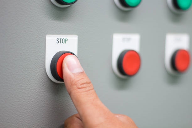
- On the panel, secondary devices are typically arranged from top to bottom in this order: indicating instruments, relays, lightboards, signal lights, pushbuttons, control switches, and necessary terminal wiring.
- Item sizes need not be drawn to full scale, but the center-to-center spacing of items must be dimensioned accurately.
 ALLPCB


