 ALLPCB


In the fast-paced world of electronics, high-density PCB designs are pushing the limits of performance, packing more power into smaller spaces. However, with great power comes great heat, and managing that heat is critical to ensuring reliability and longevity. One of the key elements in PCB thermal management is selecting the right Thermal Interface Material (TIM). But how do you choose the best TIM for high-density PCB cooling? This blog post will guide you through the essentials of TIM selection criteria, explore thermal conductivity in PCBs, and provide a practical TIM application guide to optimize PCB heat dissipation.
Whether you're designing for consumer electronics, automotive systems, or industrial applications, understanding how to manage heat effectively can make or break your project. In this comprehensive guide, we'll dive deep into the strategies and materials that ensure your PCB operates at peak performance without overheating. Let's get started.
Why Thermal Management Matters in High-Density PCB Designs
High-density PCBs are the backbone of modern electronics, enabling compact devices with powerful capabilities. However, as components are squeezed closer together and power demands increase, heat generation becomes a significant challenge. Excessive heat can degrade component performance, cause thermal stress, and even lead to system failure. Effective PCB thermal management is not just a nice-to-have; it's a necessity for reliability and safety.
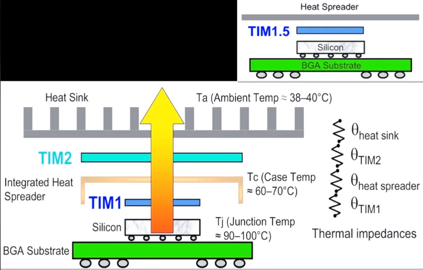
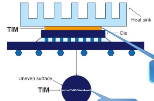
Thermal Interface Materials (TIMs) play a vital role in this process by bridging the gap between heat-generating components and heat sinks or other cooling solutions. They enhance heat transfer by filling microscopic air gaps that would otherwise act as insulators. Choosing the right TIM directly impacts how well your design handles heat, especially in high-density layouts where space is limited and temperatures can soar.
Understanding Thermal Interface Materials (TIMs) and Their Role
Thermal Interface Materials are substances applied between two surfaces to improve heat transfer. In a PCB context, TIMs are typically used between components like CPUs, GPUs, or power transistors and their cooling mechanisms, such as heat sinks or metal enclosures. TIMs come in various forms, including thermal pastes, pads, gels, and phase-change materials, each with unique properties suited to different applications.
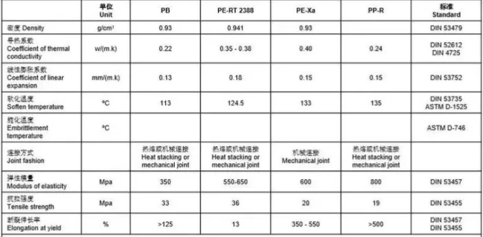
The primary goal of a TIM is to minimize thermal resistance, measured in degrees Celsius per watt (°C/W). Lower thermal resistance means better heat transfer. For high-density designs, where heat flux can exceed 50 W/cm2 in some cases, selecting a TIM with high thermal conductivity for PCBs is crucial. Typical thermal conductivity values for TIMs range from 1 W/m·K for basic thermal pads to over 10 W/m·K for advanced graphite or metal-based materials.
Beyond conductivity, TIMs must also handle other factors like ease of application, durability under thermal cycling (expansion and contraction due to temperature changes), and compatibility with the materials in your design. A poor TIM choice can lead to hotspots, reduced performance, or even mechanical failure over time.
Key TIM Selection Criteria for High-Density PCBs
Selecting the right TIM for high-density PCB cooling involves evaluating several critical factors. Below, we break down the most important TIM selection criteria to help you make an informed decision.
1. Thermal Conductivity
Thermal conductivity, measured in W/m·K, determines how efficiently a TIM transfers heat. For high-density designs, aim for materials with a conductivity of at least 3-5 W/m·K for moderate heat loads. For extreme cases, such as high-power LEDs or server processors, consider TIMs with conductivity values of 8 W/m·K or higher. Keep in mind that higher conductivity often comes with trade-offs like increased cost or reduced flexibility.
2. Thermal Resistance
Thermal resistance is influenced by the TIM’s thickness and contact pressure. A thinner TIM layer generally reduces resistance, but it must still fill surface irregularities. Many high-performance TIMs are designed to work optimally at thicknesses of 0.1 to 0.5 mm. Ensure the material maintains low resistance even under varying pressure from thermal expansion.
3. Application and Ease of Use
Consider how the TIM will be applied in your manufacturing process. Thermal pastes require precise dispensing and can be messy, while pre-cut thermal pads are easier to handle but may not conform as well to uneven surfaces. Gels and phase-change materials offer a middle ground, providing good conformability with simpler application. For high-volume production, ease of use can significantly impact cost and consistency.
4. Durability and Long-Term Stability
In high-density designs, components often undergo frequent thermal cycling, which can degrade TIM performance over time. Look for materials with low "pump-out" (the tendency to squeeze out under pressure) and high resistance to drying or cracking. Silicone-based TIMs, for instance, often provide better long-term stability compared to some non-silicone alternatives.
5. Electrical Insulation
While TIMs are primarily chosen for heat transfer, they must also prevent electrical shorts. Many TIMs are non-conductive, with dielectric strengths above 10 kV/mm, ensuring they won’t interfere with nearby circuits. If electrical conductivity is a concern in your design, verify the TIM’s specifications before use.
Practical TIM Application Guide for Optimal PCB Heat Dissipation
Choosing the right TIM is only half the battle; applying it correctly is just as important for effective PCB heat dissipation. Follow this step-by-step TIM application guide to ensure maximum thermal performance in your high-density designs.
Step 1: Surface Preparation
Start with clean, smooth surfaces on both the component and the heat sink. Remove any dust, grease, or old TIM residue using isopropyl alcohol and a lint-free cloth. Surface roughness can trap air, so consider lapping (polishing) the heat sink if it’s not already flat to within 0.001 inches (0.025 mm).
Step 2: Determine the Right TIM Amount
Apply just enough TIM to fill gaps without excess. For thermal paste, a pea-sized dot (about 1-2 mm in diameter) in the center of the component is often sufficient for small chips. For larger components, use a thin, even layer spread with a plastic card or applicator. Thermal pads should be cut to match the component’s dimensions precisely.
Step 3: Ensure Even Contact
When mounting the heat sink, apply even pressure to spread the TIM uniformly. Avoid tilting or uneven force, as this can create air pockets. Tighten mounting screws in a cross-pattern to distribute pressure evenly. For thermal pads, ensure no air bubbles are trapped during placement.
Step 4: Verify Performance
After assembly, test the system under load to monitor temperatures using thermal sensors or infrared cameras. If temperatures exceed safe limits (typically 85-100°C for most components), recheck the TIM application or consider a higher-performance material. Modern design software can also simulate heat flow to predict performance before physical testing.
Additional PCB Thermal Management Techniques for High-Density Designs
While TIM selection and application are critical, they are just one part of a broader PCB thermal management strategy. Here are additional techniques to enhance high-density PCB cooling and complement your TIM choice.
1. Use Thermal Vias
Thermal vias are small holes filled with conductive material (usually copper) that transfer heat from hot components to other layers of the PCB or to a heat sink. Placing an array of vias under a high-power component can reduce thermal resistance by up to 50%. For best results, use vias with a diameter of 0.3-0.5 mm spaced 1-2 mm apart.
2. Optimize Copper Traces and Planes
Increase the copper thickness in areas near heat sources to spread heat more effectively. A 2 oz/ft2 copper layer can handle significantly more heat than a standard 1 oz/ft2 layer. Adding dedicated copper planes for heat spreading can also lower temperatures by 10-20°C in critical areas.
3. Incorporate Heat Sinks and Fans
For high-power designs, passive heat sinks made of aluminum or copper can dissipate heat into the surrounding air. When passive cooling isn’t enough, active cooling with fans can reduce component temperatures by 30-40°C, though it adds complexity and power consumption.
4. Material Selection for PCB Substrates
Standard FR-4 substrates have a thermal conductivity of about 0.3 W/m·K, which is poor for heat transfer. For high-density designs, consider metal-core or ceramic substrates with conductivity values of 1-5 W/m·K or higher. These materials can significantly improve overall heat dissipation.
Common Challenges in TIM Selection and How to Overcome Them
Even with careful planning, challenges can arise when selecting and applying TIMs for high-density PCB cooling. Here are some common issues and solutions to ensure optimal PCB heat dissipation.
Challenge 1: Inconsistent Application
Uneven TIM application can create hotspots. Use automated dispensing equipment for thermal paste in high-volume production, or rely on pre-formed pads for consistent thickness.
Challenge 2: Degradation Over Time
TIMs can dry out or lose effectiveness after thousands of thermal cycles. Select materials rated for long-term use at your operating temperatures, and consider periodic maintenance for critical applications.
Challenge 3: Cost vs. Performance
High-performance TIMs with thermal conductivity above 8 W/m·K can be expensive. Balance cost with performance by using premium TIMs only for the hottest components and more affordable options elsewhere.
Conclusion: Building Better High-Density PCBs with the Right TIM
Optimizing PCB thermal performance is a cornerstone of successful high-density designs. By focusing on TIM selection criteria like thermal conductivity, resistance, and durability, and following a precise TIM application guide, you can achieve superior PCB heat dissipation. Combine these efforts with broader PCB thermal management techniques such as thermal vias, optimized copper layers, and advanced substrates to create designs that run cooler and last longer.
At ALLPCB, we’re committed to supporting your journey in creating high-performance electronics. With the right strategies and materials, you can tackle the heat challenges of high-density PCB cooling and build products that stand the test of time. Keep these tips in mind for your next project, and watch your designs reach new levels of efficiency and reliability.


