 ALLPCB


Overview
Industrial lens maximum compatible CCD size explained
In machine vision and industrial imaging, lens design and compatibility with the image sensor are critical. The maximum compatible CCD size is a core parameter that determines whether a lens can fully cover a sensor's imaging area, preventing image distortion or vignetting. This article explains the concept, calculation method, and practical implications of this parameter for engineers and practitioners.
CCD Size Basics
CCD (Charge-Coupled Device) is a common image sensor that captures light and converts it into digital images. In industrial contexts, CCD sizes are often expressed in inches, such as 1/4", 1/3", 1/2", 2/3", and 1". These designations do not represent the sensor's actual physical size but stem from a legacy standard based on cathode ray tube video tube diameters. The actual sensor size is measured by the diagonal length; for example, a 1/2" CCD has a diagonal of about 8 mm.
The differences in these sizes directly affect imaging resolution and field of view. Larger sensors capture more detail but require lenses that can fully cover their imaging area.
Common CCD Size Comparison
| CCD size | Width (mm) | Height (mm) | Diagonal (mm) |
|---|---|---|---|
| 1/4 inch | 3.2 | 2.4 | 4.0 |
| 1/3 inch | 4.8 | 3.6 | 6.0 |
| 1/2 inch | 6.4 | 4.8 | 8.0 |
| 2/3 inch | 8.8 | 6.6 | 11.0 |
| 1 inch | 12.8 | 9.6 | 16.0 |
Image Circle and Maximum Compatible CCD Size
The maximum compatible CCD size for an industrial lens refers to the largest sensor size the lens can cover. This parameter is based on the lens's image circle diameter, which is the diameter of the effective circular image area projected by the lens. The image circle must be greater than or equal to the sensor diagonal; otherwise, vignetting will occur and the image periphery will darken or lose information.
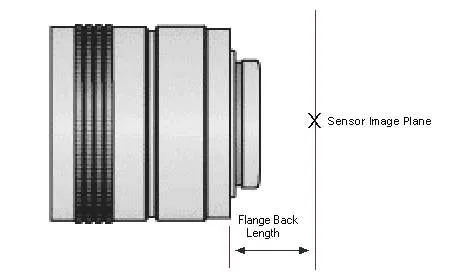
The image circle diameter is calculated as:
D = sqrt(W^2 + H^2)
Where D is the image circle diameter, W is the sensor width, and H is the sensor height. For lenses specified as compatible with a given CCD size, the image circle is designed to at least match that sensor's diagonal, often with some margin to account for manufacturing tolerances.
For example, a lens labeled compatible with a 2/3" CCD will have an image circle of at least 11 mm. Using a larger 1" CCD with a 16 mm diagonal would exceed the lens's image circle and result in reduced image quality for the sensor area outside the image circle.
Manufacturers typically specify the maximum compatible CCD size to guide lens selection. Using a sensor larger than the specified size may require special adapters or will lead to performance degradation.
How to Choose an Industrial Lens
Selecting an industrial lens requires evaluating several key factors to ensure compatibility with a machine vision system and optimal performance. First, confirm the image sensor type and size (for example, CCD or CMOS), and choose a lens whose image circle at minimum covers the sensor diagonal to avoid vignetting or image cropping. Second, determine the required field of view (FOV) and working distance. Use the focal length relationship (FOV = sensor size / focal length) to select an appropriate focal length that covers the target area without excessive distortion. Third, consider optical performance metrics such as resolution (commonly expressed in line pairs per millimeter), distortion (preferably below 1% for clear images), and the modulation transfer function (MTF), as these directly affect image quality. Fourth, evaluate the aperture (f-number) to match lighting conditions; a lower f-number allows more light for low-light scenarios but reduces depth of field. Also verify lens mount compatibility, such as C-mount or CS-mount, and account for application-specific requirements like low distortion for precision inspection or high resolution for high-speed imaging. Finally, consult manufacturer specifications and perform field tests to validate overall system performance.
Selection and Application Notes
When choosing a lens, first confirm the sensor CCD size and ensure the lens's maximum compatible size is not smaller than that value. Also consider focal length, working distance, and resolution. For precision inspection using a 1/2" CCD, for example, select a lens compatible with 1/2" or larger to achieve a wider field of view.
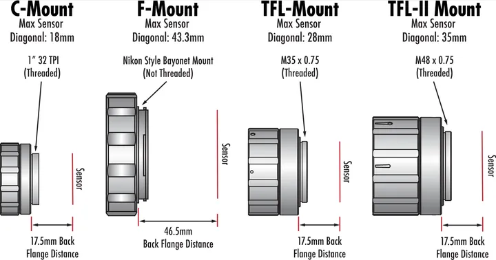
In practice, industrial lenses often use C-mount or CS-mount interfaces, and these mounts correspond to specific image circle standards for certain CCD sizes. C-mount lenses generally support larger sensor sizes such as 1", while CS-mount lenses are more suitable for smaller sensors.
Conclusion
Understanding the maximum compatible CCD size of an industrial lens helps optimize machine vision system design and performance. By matching the image circle to the sensor size, you can ensure image integrity and clarity. In engineering practice, consult manufacturer datasheets and perform field tests to verify compatibility. This parameter is not only an element of technical selection but also a key factor in ensuring reliable industrial imaging.


