Common EMC Test Parameters
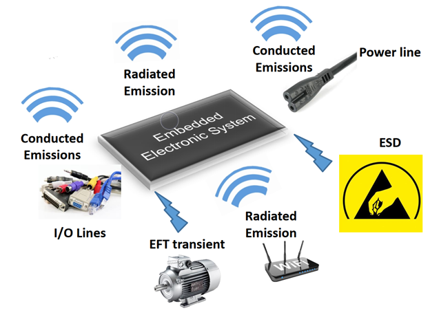
RE (Radiated Emissions, 100 kHz - 2.7 GHz): Measures radiated disturbances, which are random, broadband electromagnetic waves propagating through space from a source or interface device at frequencies outside the intended operating range.
CE (Conducted Emissions, 150 kHz - 108 MHz): Measures electromagnetic interference signals that propagate along conductive paths such as power lines, control lines, and audio cables.
RS (Radiated Susceptibility/Immunity): Radio frequency electromagnetic field immunity testing. This measures a device's ability to withstand radiated electromagnetic interference.
CS (Conducted Susceptibility/Immunity): Immunity test for conducted disturbances induced by radio-frequency fields. This measures a device's ability to withstand interference signals propagating along conductive paths.
EFT (Electrical Fast Transient): Electrical fast transient/burst immunity testing. This measures a device's ability to withstand burst-like pulse interference.
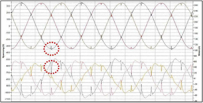
DIP (Voltage Dips): Voltage dips, short interruptions, and voltage variations immunity testing. This measures a device's ability to withstand drops in supply voltage.
ESD (Electrostatic Discharge): Electrostatic discharge immunity testing. This measures a device's ability to withstand electrostatic discharge events.
Surge: Surge immunity testing. This measures a device's ability to withstand high-energy surge currents.
Distinguishing RE from RSE
Radiated Spurious Emissions (RSE) refers to emissions generated or amplified by a mobile station at frequencies outside its operating band. These are measured when the station is connected to a non-radiating resistive load or is in receiver mode, with emissions radiating from the device's chassis, power supply, or connected cables. While most international standards classify RSE as an RF (Radio Frequency) parameter, Chinese standards typically categorize it under EMC testing.
Types of EMC Failures
EMC failures can be classified as hard failures or soft failures. A hard failure involves physical damage to components or parts. In contrast, a soft failure is a temporary malfunction that disappears after the device is power-cycled. Most EMC-related issues are soft failures.
Overlap with Reliability Failures
EMC issues can sometimes manifest as reliability failures. For example, a transient electromagnetic pulse can cause component damage. While this may appear to be a reliability problem on the surface, the root cause is often an underlying EMC issue.
EMC Failure Diagnosis Approach
The general approach to resolving an EMC failure involves two key steps: first, accurately locating the source of the failure, and second, performing an in-depth analysis of the failure mechanism. A complete resolution is only possible after thoroughly understanding this mechanism.
Various diagnostic tools can be leveraged for analysis, including dedicated EMC test instruments, spectrum analyzers, and broadband oscilloscopes. These tools are invaluable for pinpointing the fault location and understanding its characteristics.
However, a comprehensive approach combining analysis and synthesis is often the most effective method. This means considering all parts of the system, their interrelationships, and potential interactions to identify and resolve underlying EMC problems.
Common Fault Location Methods
Common methods for locating faults include fault removal and confirmation, state change confirmation, direct monitoring, and trial and error.
 ALLPCB


