 ALLPCB


Background
The frequent use of switching power supplies can generate significant electromagnetic interference (EMI) noise, affecting adjacent circuits and equipment. Passive EMI filters are a traditional solution widely used in system design to reduce noise. However, passive components like inductors and capacitors are large and heavy. Inductors also typically have a limited bandwidth, often requiring higher-order filters to achieve sufficient attenuation. With the development of third-generation power semiconductor devices and circuit topologies, the volume of passive filters has become a limiting factor in increasing power density. Using active EMI filters (AEFs) can reduce the size and weight of the filter circuit, which is a significant advantage in power-density-sensitive systems and is gaining industry attention.
Circuit Design and Experimental Validation
This work proposes a new active EMI filter (AEF) circuit. The active circuit is a transformerless design, conceptualized for simple and efficient calculation and design based on impedance mathematics. An active circuit prototype was then built based on these design parameters. It was combined with a passive EMI filter (PEF) circuit to create a hybrid EMI filter (HEF) module. Experiments on a 50W DC-DC 1/8th-brick converter show that at full load (10A), the HEF module, with its active circuit enabled, provides over 10 dB of additional noise reduction compared to using the passive filter circuit alone.
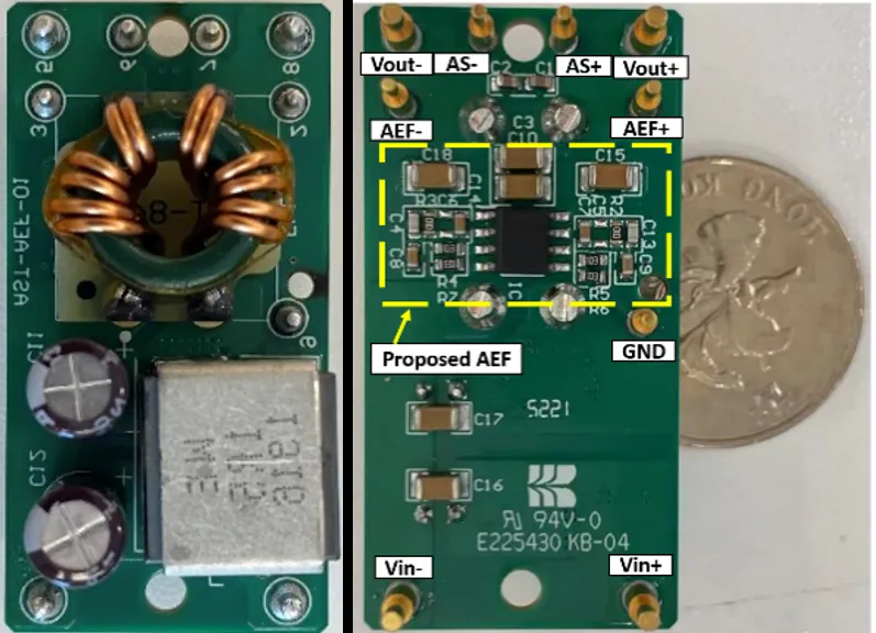
Figure 1 shows the schematic of the HEF module, which integrates the AEF into the PEF circuit for further validation and performance evaluation. A photograph of the HEF filter module is shown in Figure 2.
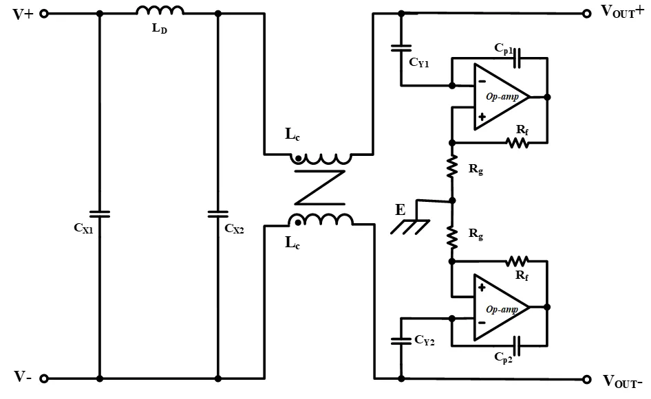
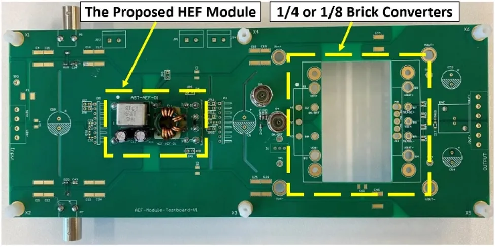
Figure 3 shows the evaluation board, which includes the HEF module and a brick DC-DC power supply.
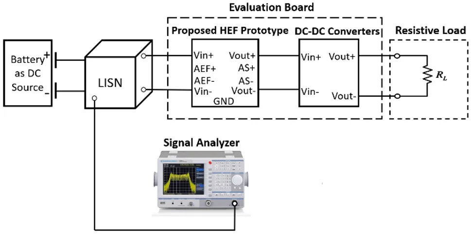
The experimental setup for EMI testing is shown in Figure 4. The test was conducted in a shielded room for conducted noise measurements and included a power supply battery, a Line Impedance Stabilization Network (LISN), the evaluation board, and a resistive load. The DC/DC switching power supply module operated under the following conditions: Vin = 12V, Vout = 5V, and Iout = 10A (full load). A 12V lead-acid battery provided the DC input power. A spectrum analyzer (Rohde & Schwarz HMS-X) was used to measure the noise level at the output terminals of the LISN (COM-POWER CORPORATION LI-125A).
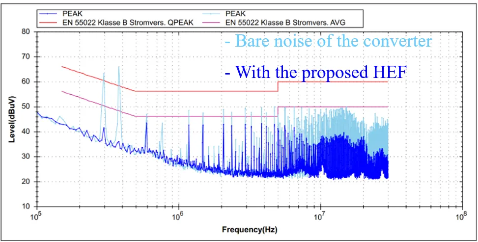
Figures 5 and 6 show the measured EMI noise spectra. In Figure 5, the light blue curve represents the baseline noise spectrum of the DC-DC converter without any filter. The dark blue curve shows the noise spectrum with the HEF module (both PEF and AEF active). In the low-frequency range (300 kHz to 500 kHz), the maximum noise reduction reaches over 30 dB. At high frequencies (approximately 7 MHz to 30 MHz), a noise reduction of about 10 dB is achieved. In the mid-frequency range, harmonic noise is reduced by more than 5 dB.
Figure 6 compares the EMI noise spectra measured with the AEF part of the HEF module powered on and off. The light blue curve represents the noise spectrum when the AEF section is powered off, meaning only the PEF component is active. The dark blue curve shows the noise spectrum with the AEF powered on, where both the PEF and AEF parts of the HEF module are active (identical to the dark blue curve in Figure 5).

The results indicate that the 30 dB noise reduction in the low-frequency range (Figure 5) is primarily from the PEF, while the 10 dB noise reduction at high frequencies (Figure 6) is mainly attributed to the AEF. This demonstrates the effectiveness of the proposed AEF circuit in the high-frequency range.
Conclusion and Future Applications
By adopting the proposed AEF technology, the size and weight of EMI filter components can be reduced, avoiding the over-design common in traditional passive solutions. This technology can also be applied to various other systems, such as AC/DC and DC/AC converters. Furthermore, since the sensing and injection points use capacitors and do not include magnetic components, the circuit has a high bandwidth. This makes it particularly suitable for noise reduction in high-frequency, high-power-density designs based on third-generation power semiconductors.


