 ALLPCB


Are you looking to build a simple IoT device from scratch? Whether you're a hobbyist or a budding engineer, assembling an IoT device using an ESP32 microcontroller can be a rewarding project. In this comprehensive guide, we’ll walk you through the process of IoT device assembly, from designing a custom PCB to soldering sensors and connecting modules for a wireless prototype. By the end, you’ll have a functional IoT device ready for real-world applications.
This tutorial focuses on actionable steps for assembling an ESP32 project, including tips for soldering sensors and ensuring proper connections for a seamless wireless prototype assembly. Let’s dive into the details of creating your own IoT device with a custom PCB!
Why Build an IoT Device with ESP32?
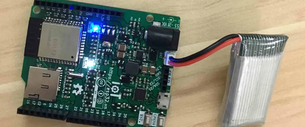
The ESP32 microcontroller is a popular choice for IoT projects due to its built-in Wi-Fi and Bluetooth capabilities, dual-core processor, and low cost—often under $10 for a basic development board. It’s perfect for beginners and professionals alike who want to create connected devices for home automation, environmental monitoring, or other smart applications. With its 30 GPIO pins, it supports a wide range of sensors and modules, making it highly versatile for IoT device assembly.
In this guide, we’ll use the ESP32 as the core of our project, walking you through each step of assembling a wireless prototype with a custom PCB. This hands-on approach will help you understand the fundamentals of connecting modules and soldering components effectively.
What You’ll Need for IoT Device Assembly
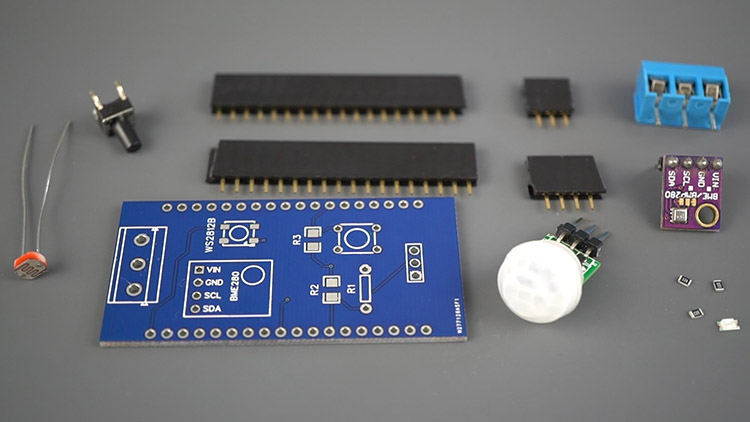
Before starting your ESP32 project, gather the necessary tools and components. Having everything ready will make the process smoother and more efficient. Here’s a list of what you’ll need for assembling your wireless prototype:
- ESP32 Development Board: The heart of your IoT device, providing processing power and connectivity.
- Sensors: For this tutorial, we’ll use a DHT11 temperature and humidity sensor (costing around $2-3) as an example.
- Custom PCB: Designed to house the ESP32 and connect your sensors and modules. You can design this using popular EDA software.
- Soldering Tools: A soldering iron (25-40W), solder wire (0.8mm diameter recommended), and flux for clean joints.
- Breadboard and Jumper Wires: For prototyping and testing connections before soldering.
- Power Supply: A 5V USB power source or a 3.3V regulator for the ESP32.
- Resistors and Capacitors: For stabilizing sensor signals (e.g., a 4.7kΩ resistor for the DHT11 data pin).
- Multimeter: To check voltages and continuity during assembly.
- Programming Tools: A USB cable to upload code to the ESP32 using the Arduino IDE or similar software.
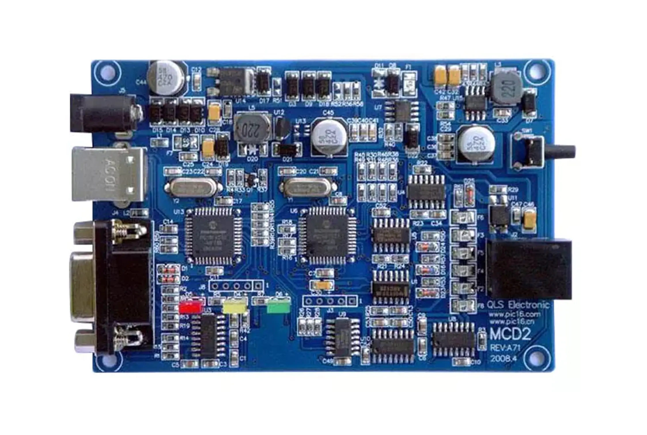
Step 1: Designing Your PCB for IoT Device Assembly
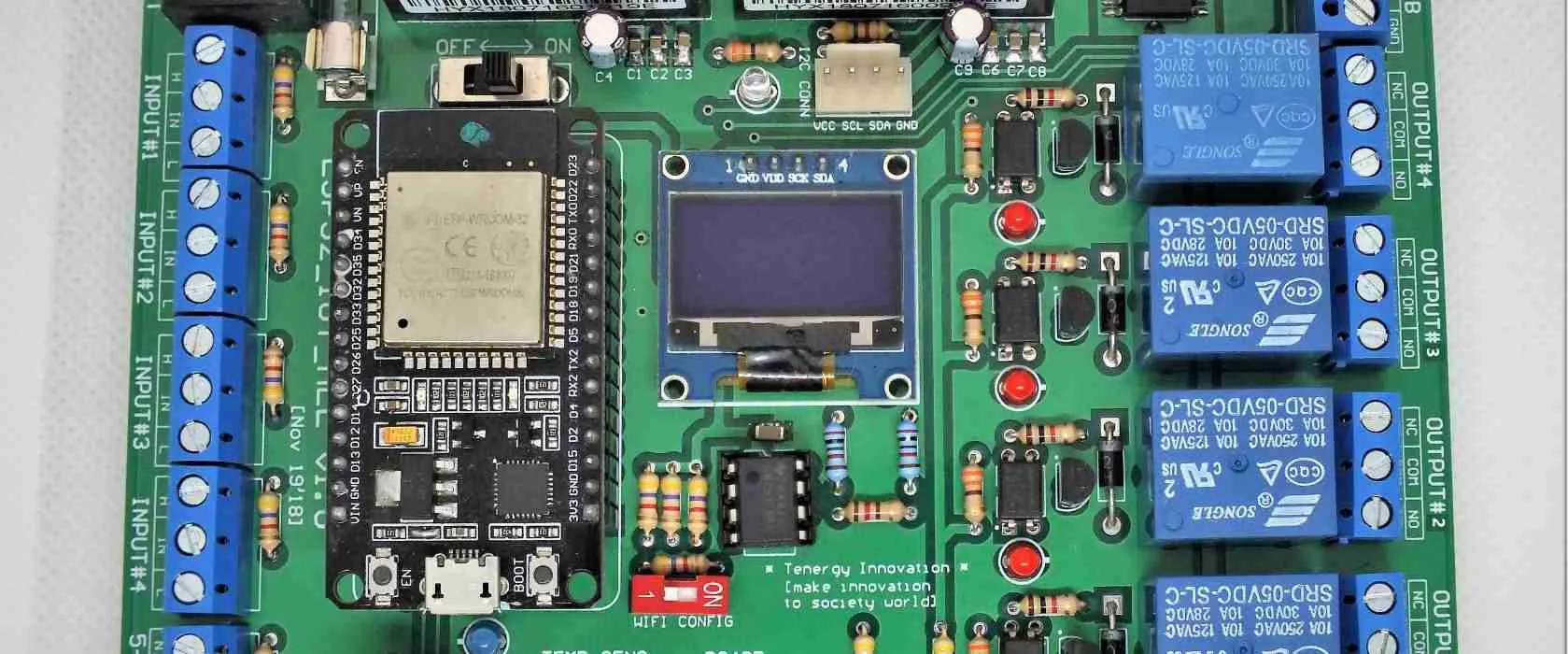
The first step in assembling an ESP32 project is designing a custom PCB to integrate all components neatly. A well-designed PCB reduces wiring clutter and improves the reliability of your wireless prototype assembly.
Start by creating a schematic that includes the ESP32 as the central component. Map out connections for power (3.3V and GND), GPIO pins for sensors, and any additional modules like LEDs or relays. For example, connect the DHT11 sensor’s data pin to GPIO 4 on the ESP32, with a 4.7kΩ pull-up resistor between the data pin and the 3.3V line to ensure stable signal transmission.
Once your schematic is ready, convert it into a PCB layout. Place the ESP32 in the center for easy access to pins, and position the sensor and other components nearby to minimize trace lengths. Keep power traces wider (at least 20 mils) to handle current without voltage drops, and ensure a ground plane to reduce noise—critical for IoT devices operating at 2.4 GHz for Wi-Fi.
After finalizing the design, export the Gerber files and send them for fabrication. When you receive your PCB, inspect it for any manufacturing defects before proceeding with assembly.
Step 2: Prototyping Your Circuit on a Breadboard
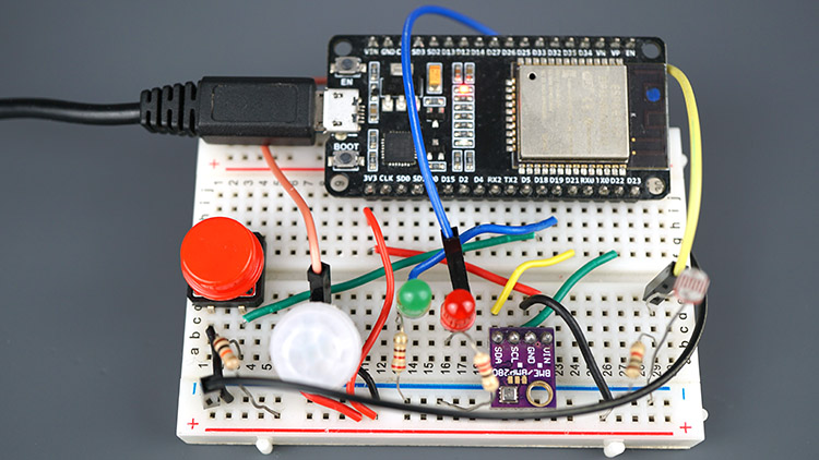
Before soldering components onto your PCB, prototype the circuit on a breadboard. This step helps verify connections and troubleshoot issues without risking damage to your custom board during wireless prototype assembly.
Place the ESP32 on the breadboard and connect the DHT11 sensor. Wire the sensor’s VCC to 3.3V, GND to GND, and data pin to GPIO 4 with the pull-up resistor. Use a multimeter to confirm the voltage across VCC and GND is around 3.3V, as the ESP32 operates at this level and exceeding it (e.g., 5V) can damage the board.
Upload a simple test code to the ESP32 using the Arduino IDE to read data from the DHT11. If the sensor outputs temperature and humidity values (e.g., 25°C and 60% humidity), your connections are correct. If not, double-check wiring and resistor values.
Step 3: Soldering Sensors and Components onto the PCB
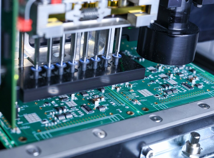
With the prototype working, it’s time to move to soldering sensors and components onto your custom PCB. Soldering is a critical skill for IoT device assembly, ensuring secure and reliable connections.
Start by soldering the ESP32 module or its pin headers to the PCB. Use a soldering iron at around 300°C to avoid overheating components. Apply flux to the pads for better solder flow, and use a small amount of solder (about 1mm of 0.8mm wire per joint) to create clean, shiny connections. Avoid cold solder joints, which look dull and can cause intermittent issues.
Next, solder the DHT11 sensor or its pin headers. Ensure the orientation matches your PCB design, and secure the sensor with a small dab of hot glue if needed for stability. Add the pull-up resistor and any decoupling capacitors (e.g., a 0.1μF capacitor near the ESP32 power pins) to filter noise.
Finally, inspect each solder joint with a magnifying glass for bridges or cracks. Use a multimeter to test continuity between connected points, confirming there are no open circuits.
Step 4: Connecting Modules for Wireless Functionality
Connecting modules correctly is essential for a functional wireless prototype assembly. Since the ESP32 already has built-in Wi-Fi and Bluetooth, no external modules are needed for basic connectivity. However, you may want to add components like an OLED display or additional sensors for enhanced functionality.
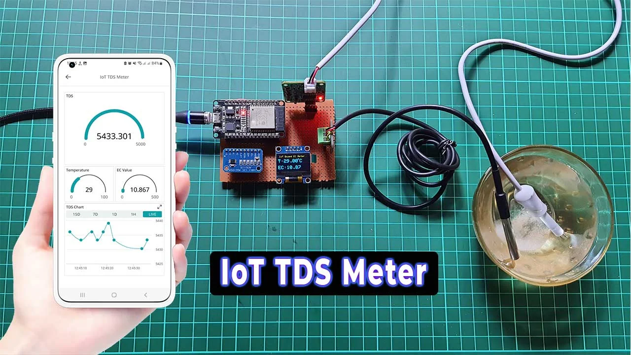
For example, if you’re adding a 0.96-inch OLED display to show sensor data, connect it via the I2C protocol. Solder the display’s SDA pin to GPIO 21 and SCL pin to GPIO 22 on the ESP32, with VCC to 3.3V and GND to GND. These pins are the default I2C pins for most ESP32 boards, ensuring reliable communication at speeds up to 400 kHz.
After connecting modules, re-upload your test code to include display output or additional sensor readings. Verify that data from the DHT11 appears on the OLED (e.g., "Temp: 25°C, Humidity: 60%"). If there’s no output, check for loose connections or incorrect pin assignments.
Step 5: Testing and Troubleshooting Your IoT Device
Once all components are soldered and modules connected, perform a full test of your IoT device. Power up the board using a 5V USB cable or a 3.3V regulator, and monitor the ESP32’s onboard LED for signs of activity. Upload your final code to read sensor data and transmit it over Wi-Fi to a local server or cloud platform.
For instance, configure the ESP32 to send DHT11 readings every 10 seconds to a free IoT platform using MQTT protocol. Check if the data appears on the platform’s dashboard. If transmission fails, verify your Wi-Fi credentials and ensure the ESP32’s antenna isn’t obstructed, as signal strength can drop below -80 dBm in noisy environments, causing connection issues.
Use a multimeter to measure voltages at key points. The ESP32 should receive 3.3V ± 0.3V, and sensor signals should be within expected ranges (e.g., DHT11 data pin toggling between 0V and 3.3V). If you encounter errors, recheck solder joints and code logic.
Step 6: Finalizing Your Wireless Prototype Assembly
With testing complete, finalize your wireless prototype assembly by securing components and preparing the device for deployment. Use standoffs or a small enclosure to protect the PCB from dust and physical damage. Ensure ventilation if the device will be in a warm environment, as the ESP32 can heat up to 50°C under heavy load.
Label the PCB or enclosure with port names and power ratings for future reference. Document your pin connections and code in a project log, especially if you plan to scale or modify the device later. This documentation is invaluable for troubleshooting or upgrading your IoT device.
Tips for Successful IoT Device Assembly
Here are some additional tips to ensure success when assembling an ESP32 project:
- Double-Check Polarity: Always verify the polarity of components like capacitors and diodes before soldering to avoid damage.
- Use Heat Sinks: When soldering near the ESP32, use a heat sink clip to prevent overheating sensitive areas.
- Keep Traces Short: Minimize trace lengths for high-frequency signals (like Wi-Fi) to reduce interference and signal loss.
- Test Incrementally: Test after each major step (e.g., after soldering the ESP32, then after adding sensors) to catch issues early.
- Update Firmware: Ensure the ESP32 firmware is up to date for optimal performance and security during wireless operations.
Conclusion: Start Building Your IoT Device Today
Building a simple IoT device through IoT device assembly is an exciting way to explore electronics and connected technologies. By following this step-by-step PCB assembly tutorial, you’ve learned how to design a custom PCB, prototype on a breadboard, solder sensors, connect modules, and finalize a wireless prototype assembly with an ESP32 at its core.
Whether you’re creating a smart home sensor or a weather monitoring station, the skills of assembling an ESP32 project and soldering components will serve you well in future endeavors. With a custom PCB, your device becomes more reliable and professional, opening doors to endless IoT possibilities.
Take the knowledge from this guide and start your next project with confidence. The world of IoT is at your fingertips, and with each build, you’ll gain more expertise in creating innovative solutions!


