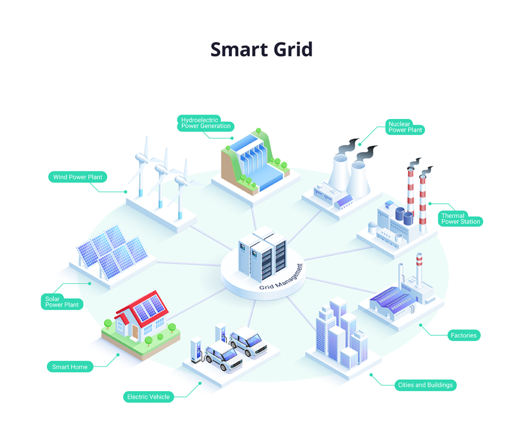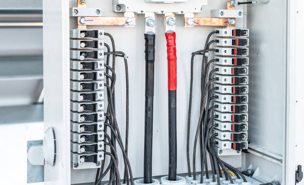
These 40 secondary-circuit concepts are fundamental skills electrical workers and technicians should be familiar with.
1. Difference between computer-based protection and traditional relay protection
The main difference is that traditional protection inputs are current and voltage signals processed in the analog domain, comparing measured analog quantities with preset thresholds inside the device. Computers perform digital arithmetic and logic operations rather than direct analog comparisons.
2. How are the zones of zero-sequence current protection divided?
The zero-sequence I stage is set to the maximum zero-sequence current that should be passed by protection when a line-end grounded short circuit occurs; it does not cover the entire line length but should be no less than 15%–20% of the protected line. The zero-sequence II stage generally covers the full line length and extends into the I-stage zone of adjacent lines to coordinate with them. The zero-sequence III stage is the backup for I and II stages and coordinates with adjacent lines.
3. What is reclose acceleration after reclosing?
When a line fault occurs and protection trips the line breaker, the reclosing device operates immediately. If the fault is transient, the fault disappears after breaker opening and the reclosing succeeds, restoring supply. If the fault is permanent, after reclosing the timed protection elements are bypassed so they effectively trip with zero time delay, causing an accelerated trip to clear the fault. This is reclosing followed by accelerated trip when the fault persists.
4. What should be done after mistakenly operating an isolating switch?
(1) If an isolator is pulled and an arc appears just after the blade leaves the stationary contact, immediately closing it can extinguish the arc and avoid an incident. If the blade has been fully opened, the mistakenly opened isolator must not be closed again.
(2) If an isolator was mistakenly closed and an arc occurred during closing, it must not be opened again, because opening a load-carrying isolator could cause a three-phase arc short circuit.
5. What is R, L, C parallel resonance?
A circuit with resistor, inductor, and capacitor in parallel, driven by a sinusoidal source at a particular frequency, can reach a state where the terminal voltage and total current are in phase and the whole circuit behaves as a pure resistance. This condition is called parallel resonance.
6. Advantages of using negative-sequence and zero-sequence incremental elements as distance protection trip elements
(1) High sensitivity;
(2) Can serve as the trip element for an oscillation-blocking device;
(3) Will not operate incorrectly when secondary voltage circuits are interrupted;
(4) The occurrence of symmetrical components is independent of faulted phase, so a single relay can serve as the trip element, simplifying design.
7. Under what conditions can protection equipment be classified as Class I?
All protection equipment of a Class I installation must be in good technical condition, fully meet system safety operation requirements, and satisfy these main conditions:
(1) Protection panels, relays, components, accessories, and secondary circuits have no defects;
(2) Device principles, wiring, and settings are correct and comply with applicable regulations and anti-accident measures;
(3) Documentation and drawings are complete and match actual installation;
(4) Operating conditions are good.
8. What items should be inspected for control switches?
Inspection items include:
(1) Enclosure is clean, free of oil, intact, and undamaged;
(2) Mounting is secure and the device does not move during operation;
(3) Sealing cover seals effectively;
(4) All connection terminals are firmly connected, not loose or corroded;
(5) Mechanism moves freely, positions are correct, and contacts are good;
(6) After opening the sealing cover and inspecting with a flashlight, the interior should be clean, lubricants not dried, contact points not burnt. Test contact pressure with an insulating stick; pressure should be adequate.
9. What should be checked for transformer differential protection during no-load energization?
For newly installed transformer differential protection, perform five no-load energizations at rated voltage. Before energization, check secondary wiring and ensure correctness. Perform the test on the high-voltage source side and the low-voltage side, because system impedance and transformer leakage reactance limit inrush current. The high-source side typically has lower system impedance and the transformer's low-voltage winding is usually inside with smaller leakage reactance, so energizing at source and low-voltage sides causes larger inrush. Protection should not operate during these tests; if it does, increase the relay pickup current.
10. What measures should be taken when disconnecting secondary wiring?
Keep records when disconnecting secondary wiring; cancel them in the log when restoring. When many secondary wires are changed, label each conductor. When removing or laying secondary cables, tag the cable ends and label at bends and crossing points.
11. What anti-accident measures are required for gas protection relays?
(1) Convert the lower float structure of the gas relay to a baffle type and change contacts to vertical to improve heavy-gas operation reliability;
(2) To prevent rainwater shorting of gas relays, apply rainproof measures at their ends and at terminals inside the cable lead terminal box;
(3) Use oil-resistant lead wires for gas relay output wires;
(4) Relay outgoing leads and cable cores should be connected separately to terminals inside the cable lead terminal box.
12. General principles for transformer protection design
(1) Gas protection to defend against internal tank short circuit and oil level decrease;
(2) Longitudinal differential protection or instantaneous overcurrent protection to defend inter-phase faults in windings and leads, earth faults on the network-side winding leads with large ground current, and inter-turn faults;
(3) Overcurrent protection for external phase faults, serving as gas protection and longitudinal differential backup (or overcurrent with composite voltage start or negative-sequence current protection);
(4) Zero-sequence current protection to defend external earth faults with large ground current in the network;
(5) Overload protection to defend against sustained symmetric overloads.
13. Functions of the distance protection starting element
(1) Quickly initiate protection during short-circuit faults;
(2) Actuate oscillation-blocking devices or serve as the measuring element for the third zone;
(3) Support zone switching;
(4) Support phase selection switching;
(5) In solid-state protections, if the DC logic part fails, lock the entire protection.
14. What protections are typically installed on 10 kV transmission lines?
(1) Phase-to-phase fault protection: single-supply lines typically use two-stage overcurrent protection, i.e. instantaneous overcurrent and definite-time overcurrent; double-supply lines generally use directional or non-directional overcurrent and instantaneous overcurrent protection;
(2) Earth fault protection: commonly include non-selective insulation monitoring, zero-sequence overvoltage protection, and power-directional protection.
15. How does negative feedback affect amplifier performance?
(1) Reduces gain;
(2) Improves gain stability;
(3) Improves waveform distortion;
(4) Widens bandwidth;
(5) Changes input and output resistances of the amplifier.
16. Causes of non-sinusoidal currents
Non-sinusoidal currents can be caused by the source or the load. Typical causes:
(1) Several different sinusoidal emf sources act simultaneously, or AC and DC emfs coexist;
(2) Presence of non-sinusoidal periodic emfs in the circuit;
(3) Nonlinear elements in the circuit.
17. Why are surge arresters in 6–35 kV systems selected by rated line voltage?
6–35 kV systems typically have small ground-fault current. Under normal conditions, arresters see phase-to-ground voltage. Under a single-phase-to-ground fault, the healthy phases' phase-to-ground voltages rise to line voltage, and such faults may persist for some time. Arresters should not operate under these conditions, so arrester rated voltage must be chosen according to the system's rated line voltage rather than the rated phase-to-ground voltage.
18. Under what conditions is protection equipment classified as Class III?
Class III indicates protection equipment is incomplete or performs poorly, thus affecting system safety. Main protection equipment meeting any of the following is also rated Class III:
(1) Protection does not meet system requirements and may cause system oscillation, cascading failures, or severe damage to major equipment during faults;
(2) Does not meet anti-accident measure requirements;
(3) Operating items for staff such as links, handles, and buttons are not labeled;
(4) Drawings are incomplete and do not match reality;
(5) Fault recorders cannot reliably record or are not in service.
19. What environmental conditions should be controlled during relay testing?
Test environmental requirements include temperature, relative humidity, and atmospheric pressure. These conditions affect relay performance and test instruments. Recommended conditions:
(1) Temperature: 15–35°C;
(2) Humidity: 45–75% RH;
(3) Atmospheric pressure: 660–780 mmHg.
20. Principles for selecting test instruments
(1) Choose instrument type according to the object under test: select DC or AC instruments depending on whether relays are DC or AC type;
(2) Choose instrument internal resistance based on test circuit and relay coil impedance;
(3) Choose instrument range according to measurement magnitude;
(4) Choose instruments appropriate for the site and working conditions.
21. Main acceptance items after completion of new protection installations
Acceptance items include:
(1) Electrical equipment and line measured parameters are complete and correct;
(2) As-built protection drawings match actual installation;
(3) Checked relay settings meet the setting notice requirements;
(4) Test items and results comply with testing regulations and relevant procedures;
(5) Verify CT ratios and V-A characteristics; secondary loading meets error requirements;
(6) Inspect front and rear of panels for neatness, intact equipment, good circuit insulation, and correct markings;
(7) Perform acceptance tests using primary load current and working voltage to verify CT polarity, ratio, circuit correctness, direction, and correctness of elements and wiring for differential, distance, overfrequency, and other protections.
22. How to check the zero-sequence voltage circuit for directional zero-sequence protection in a large ground-current system during normal operation?
To ensure correct operation of the directional zero-sequence protection, perform an integrity check of the zero-sequence voltage circuit. Use the test small bus taken from the secondary winding of a VT connected in open delta; measure the voltage on the protection zero-sequence voltage bus YMN for each set. If each measures 100 V, the circuit is normal.
23. In a small ground-current radial network, how do faulted and non-faulted line currents differ during a single-phase-to-ground fault?
At the sending end of the faulted line, the measured zero-sequence current is the zero-sequence capacitive current of that line, equal to the sum of other lines' zero-sequence capacitive currents and flowing into the bus. At the sending end of a non-faulted line, the measured zero-sequence current is that line's healthy-phase-to-ground capacitive current and flows out of the bus.
24. Why are phase-to-phase protection time settings longer than zero-sequence protection in large ground-current systems?
Protection time settings are typically stepped. Phase-to-phase protection time is set with stepwise increases from the user toward the source for each protection stage. Zero-sequence protection, however, often does not need to coordinate with transformer low-voltage users because power transformers are commonly Y/d connected; when a low-voltage-side ground fault occurs, the high-voltage side has no zero-sequence current. Therefore, zero-sequence protection times are generally shorter than phase-to-phase protection times.
25. What is power system oscillation and typical causes?
Oscillation refers to loss of synchronism between two parallel-running systems or generating plants. Causes include long fault clearance times leading to loss of dynamic stability; in weakly interconnected systems, misoperation, generator demagnetization, tripping of a generator, or disconnection of a line or equipment can also cause oscillation.
26. What requirements should a modulator satisfy?
(1) When input DC signal Ui = 0, output U0 = 0;
(2) The amplitude of the AC output should be proportional to the magnitude of the DC input;
(3) When the polarity of DC input Ui reverses, the phase of the AC output should change accordingly.
27. Principles for configuring phase-to-phase fault protection in 35 kV isolated neutral networks
Configuration principles:
(1) If using two-phase current protection, CTs should be installed on the two corresponding phases (for example A and C);
(2) Protection should be configured with remote backup;
(3) If a line fault would reduce voltages at plant auxiliary buses, main source tie buses, or important user buses below 50%–60% of rated voltage, the fault should be cleared rapidly.
28. Purpose of high-frequency protection on high-voltage networks
High-frequency protection is applied to long high-voltage transmission lines. It enables instantaneous tripping from both ends for faults at any point on the protected line, thereby improving system stability and reclosing success rate.
29. Why are phase-to-phase protection times longer than zero-sequence protection in large ground-current systems?
Time settings follow a stepped coordination principle. Phase-to-phase protection time increases stepwise from user toward source for each protection stage. Zero-sequence protection typically does not need to coordinate with transformer low-voltage users because many step-down transformers are Y/d11 connected; when a low-voltage-side ground fault occurs, the high-voltage side has no zero-sequence current. Thus, zero-sequence protection times are shorter than phase-to-phase protection times.
30. Basic requirements for operational amplifiers
(1) Input impedance and feedback network impedance values should be accurate and stable;
(2) Open-loop voltage gain should be sufficiently large;
(3) Open-loop input resistance ri should be large;
(4) Open-loop output resistance should be small;
(5) Zero drift and noise should be small.
31. What is amplifier output resistance?
At the amplifier output, the amplifier can be modeled as a signal source with a certain internal resistance; this internal resistance is the output resistance.
32. What should be noted when using the superposition principle for linear circuits?
When applying superposition, calculate each branch voltage and current separately for each voltage or current source acting alone, then algebraically sum the results. Notes:
(1) Superposition only applies to linear circuits; it is not applicable to nonlinear circuits;
(2) Pay attention to polarity and direction when summing currents and voltages; use algebraic sums;
(3) Circuit connections and resistor values must remain unchanged. When considering a current source, short voltage sources; when considering a voltage source, open current sources;
(4) Superposition applies to voltages and currents only; power cannot be obtained by direct superposition.
33. Why do hydro generators need overvoltage protection?
Hydraulic turbine governors respond slowly; after a sudden loss of load the generator can experience excessive overvoltage. Therefore, overvoltage protection is required.
34. What are underexcitation and demagnetization of a generator?
Underexcitation denotes generator excitation current below the steady-state stability limit. Demagnetization refers to the loss of generator excitation current.
35. Why install generator overcurrent protection driven by load-voltage, and why use a CT at the generator neutral?
This protection serves as backup for generator differential protection or for downstream elements. It operates in cases such as:
(1) External short circuit where primary protective devices or relays fail to operate;
(2) Faults inside the generator differential protection zone where differential protection refuses to trip.
Using a CT at the generator neutral allows detection of unbalanced currents and provides appropriate sensitivity for these conditions.
36. How is the negative-sequence voltage setting generally chosen for transformer composite-voltage-start overcurrent protection?
Under normal operation, three-phase voltage is primarily positive-sequence with very small negative-sequence. The negative-sequence voltage element setting is based on the output imbalance voltage of the normal negative-sequence voltage filter, typically set to 6–12 V on the secondary.
37. Why do some large transformers and system tie transformers use negative-sequence current and single-phase low-voltage start overcurrent protection as backup?
Advantages of this backup protection:
(1) High sensitivity for asymmetric faults;
(2) Sensitivity to downstream asymmetric faults is independent of transformer connection type.
38. Role of intermediate relays in protection schemes
(1) Measurement element contacts in protection devices are often small in size and few in number. Intermediate relays increase contact capacity and quantity;
(2) When tube-type arresters are installed on a line, intermediate relays can provide a delay to prevent false operation of fast protection caused by arrester discharge;
(3) They satisfy protection logic circuit requirements.
39. Differences in operating conditions between electromagnetic current relays and voltage relays
Voltage relays are generally connected on the VT secondary. Compared to CT circuits, voltage relays have higher voltage, so relay coils have more turns, thinner wire, and larger impedance; coil reactance increases and coil current decreases. At the same time, magnetic circuit reluctance decreases so the decrease in current and decrease in reluctance compensate and the electromagnetic torque during operation remains effectively constant, resulting in loss of typical relay characteristics.
40. Why is the distance protection reach largely unaffected by changes in system operation?
Distance protection uses the ratio of line-end voltage to current as its criterion. Since fault impedance depends primarily on the distance from the line origin to the fault point, the protection reach is essentially independent of changes in overall system operating conditions.
 ALLPCB


