 ALLPCB


Designing flexible printed circuit boards (Flex PCBs) can be a game-changer for compact, lightweight, and innovative electronics. However, ensuring reliability in Flex PCB designs requires careful attention to Design for Manufacturability (DFM) principles. If you're looking for a flex PCB design checklist, DFM guidelines for flexible circuits, or ways to avoid flex PCB manufacturing errors, this guide is for you. We'll also cover how to enhance reliability in Flex PCB and align with IPC standards for Flex PCB design.
In this comprehensive blog, we'll walk you through a detailed DFM checklist tailored for Flex PCBs. From material selection to layout optimization, you'll find actionable steps to minimize errors and maximize performance. Let's dive into the essentials of designing reliable flexible circuits.
Why DFM Matters for Flex PCB Reliability
Flex PCBs are unique due to their ability to bend and conform to tight spaces, making them ideal for applications like wearables, medical devices, and aerospace systems. However, their flexibility introduces unique challenges, such as stress on traces during bending and potential manufacturing defects. This is where Design for Manufacturability (DFM) comes in. DFM ensures that your design is optimized for production, reducing the risk of flex PCB manufacturing errors and improving reliability in Flex PCB applications.
By following DFM guidelines, you can avoid costly redesigns, delays, and failures in the field. A well-thought-out design not only meets functional requirements but also aligns with manufacturing capabilities, ensuring a smoother transition from prototype to production.
Understanding Flex PCB Basics Before Designing
Before diving into the checklist, let’s cover the fundamentals of Flex PCBs. Unlike rigid boards, Flex PCBs use materials like polyimide or polyester, which allow bending without breaking. They often have thinner copper layers (typically 0.5 oz to 2 oz, or 17 to 70 micrometers) and require special attention to stack-up design to maintain signal integrity and durability.
Flex PCBs can be single-sided, double-sided, or multilayer, and they may include rigid-flex configurations where flexible and rigid sections are combined. The bending radius, often as tight as 10 times the board thickness, is a critical factor in design to prevent cracking or delamination. Understanding these basics sets the stage for applying DFM guidelines for flexible circuits.
Comprehensive DFM Checklist for Flex PCB Designs
Below is a step-by-step flex PCB design checklist to guide you through the process of creating reliable and manufacturable flexible circuits. Each point is crafted to address common pitfalls and enhance performance.
1. Material Selection for Durability and Flexibility
Choosing the right materials is the foundation of a reliable Flex PCB. Polyimide is the most common substrate due to its high thermal stability (up to 260°C) and flexibility. However, for cost-sensitive projects, polyester can be an alternative, though it has lower heat resistance (around 150°C).
- Opt for adhesive-less copper-clad laminates to reduce stress during bending and improve reliability.
- Consider coverlay materials (like polyimide films) over liquid photoimageable solder masks for better flexibility and protection.
- Ensure material thickness matches the bending requirements—thinner materials (e.g., 25 micrometers) for tighter bends, thicker ones (e.g., 50 micrometers) for moderate flexibility.
Selecting materials with mismatched thermal expansion coefficients can lead to delamination during manufacturing or operation, a common flex PCB manufacturing error.
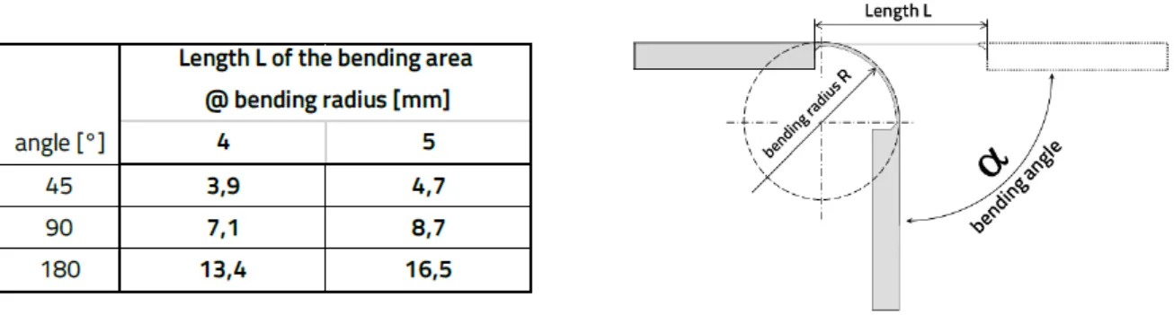
2. Define Bend Radius and Flex Areas Early
The bend radius determines how much stress the Flex PCB can handle without damage. A general rule of thumb is to maintain a bend radius of at least 10 times the thickness of the flex material for dynamic applications (repeated bending) and 6 times for static applications (one-time bending during assembly).
- Avoid placing vias, components, or solder joints in bend areas to prevent cracking.
- Use gradual curves instead of sharp bends in the layout to distribute stress evenly.
- Simulate bending in 3D modeling software to predict stress points before finalizing the design.
3. Optimize Trace and Via Design for Flexibility
Traces on Flex PCBs endure mechanical stress during bending, so their design must prioritize durability. Narrow traces are more prone to cracking, especially in dynamic flex areas.
- Use wider traces (minimum 6-8 mils or 0.15-0.2 mm) in flex regions to reduce the risk of breakage.
- Route traces perpendicular to the bend line to minimize stress concentration.
- Add teardrop pads at via connections to prevent cracking under stress.
- Avoid vias in flex zones; if unavoidable, ensure they are reinforced with annular rings at least 10 mils (0.25 mm) larger than the via diameter.
Signal integrity is another concern. For high-speed signals, maintain controlled impedance (often 50 ohms for single-ended traces or 100 ohms for differential pairs) by adjusting trace width and spacing based on the dielectric constant of the substrate (typically 3.2-3.5 for polyimide).
4. Incorporate Stiffeners for Support
Stiffeners are rigid materials (like FR4 or polyimide) added to specific areas of a Flex PCB to provide mechanical support for components or connectors. Without stiffeners, heavy components can cause stress fractures during bending.
- Place stiffeners under high-density component areas or connectors to prevent flexing.
- Ensure stiffener thickness (typically 0.2-0.8 mm) matches the mechanical load requirements.
- Avoid overlapping stiffeners with flex zones to maintain flexibility.
5. Follow IPC Standards for Flex PCB Design
Adhering to IPC standards for Flex PCB design is non-negotiable for ensuring quality and reliability. The IPC-2223 standard provides detailed guidelines for flexible and rigid-flex PCB design, covering aspects like bend radius, material selection, and trace routing.
- Refer to IPC-2223 for minimum bend radius and stack-up recommendations.
- Use IPC-6013 for performance and testing criteria to validate your design’s reliability.
- Ensure compliance with IPC-9204 for mechanical and electrical testing of flexible circuits.
Following these standards not only improves reliability in Flex PCB but also ensures compatibility with manufacturing processes, reducing the likelihood of errors.
6. Minimize Component Placement Risks
Component placement on Flex PCBs requires careful planning to avoid mechanical stress and manufacturing issues. Heavy or large components can cause uneven stress distribution, leading to failures.
- Place components on rigid or stiffened areas whenever possible.
- Avoid placing components near bend lines or high-stress zones.
- Use lightweight, low-profile components to reduce mechanical load (e.g., 0201 or 0402 SMD packages).
7. Design for Manufacturing Tolerances
Flex PCB manufacturing involves tight tolerances due to the thin materials and precise processes. Misalignments or overly tight specifications can result in flex PCB manufacturing errors like misregistered layers or incomplete etching.
- Provide clear spacing between traces and pads (minimum 5 mils or 0.13 mm) to account for etching tolerances.
- Specify realistic tolerances for via drilling (e.g., ±3 mils or 0.08 mm) to avoid drill wander.
- Include fiducial markers for accurate layer alignment during fabrication.
8. Test and Validate Your Design
Testing is a critical step in ensuring reliability in Flex PCB. Before moving to full-scale production, validate your design through simulations and prototypes.
- Perform thermal cycling tests (e.g., -40°C to 85°C) to check for delamination or cracking.
- Conduct bend testing (e.g., 10,000 cycles at the specified radius) to verify durability in dynamic applications.
- Use electrical testing to confirm signal integrity, especially for high-speed designs with impedance requirements.
Common Flex PCB Manufacturing Errors and How to Avoid Them
Even with a solid design, manufacturing errors can compromise the performance of Flex PCBs. Here are some frequent flex PCB manufacturing errors and tips to prevent them using DFM guidelines for flexible circuits.
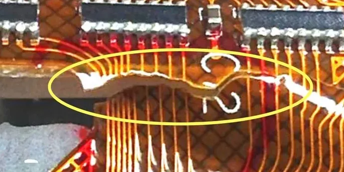
- Delamination: Caused by mismatched materials or poor adhesion. Use adhesive-less laminates and ensure compatible thermal expansion coefficients.
- Trace Cracking: Often due to sharp bends or narrow traces in flex areas. Follow bend radius guidelines and use wider traces as mentioned earlier.
- Misalignment: Occurs during multilayer stacking. Include fiducial markers and allow for manufacturing tolerances in your design.
- Incomplete Etching: Results in short circuits or weak traces. Provide adequate spacing and avoid overly fine features (below 3 mils or 0.08 mm).
Enhancing Reliability in Flex PCB Applications
To achieve long-term reliability in Flex PCB, consider the end-use environment during the design phase. For example:
- In automotive applications, design for vibration resistance by using thicker materials (e.g., 50 micrometers) and reinforced vias.
- For medical devices, prioritize biocompatibility by selecting materials compliant with ISO 10993 standards.
- In aerospace, ensure thermal stability for extreme conditions (e.g., -55°C to 125°C) by using high-grade polyimide.
Additionally, collaborate closely with your manufacturing partner to align your design with their capabilities. Share detailed documentation, including stack-up details, material specifications, and testing requirements, to minimize miscommunication.
Conclusion: Building Reliable Flex PCBs with DFM
Designing Flex PCBs that are both reliable and manufacturable doesn’t have to be daunting. By following this flex PCB design checklist and adhering to DFM guidelines for flexible circuits, you can avoid common flex PCB manufacturing errors and ensure reliability in Flex PCB applications. Aligning with IPC standards for Flex PCB design further guarantees quality and compatibility with industry best practices.
Start with the right materials, define flex areas carefully, optimize trace layouts, and validate your design through testing. These steps will help you create flexible circuits that perform flawlessly in even the most demanding applications. With a focus on DFM, you’re not just designing a PCB—you’re unlocking reliability for your next innovation.


