 ALLPCB


If you're dealing with a malfunctioning network switch and suspect issues with its printed circuit board (PCB), you're in the right place. This guide offers a practical approach to network switch PCB troubleshooting, helping you identify and resolve common problems like component failure, signal integrity issues, and power distribution problems. Whether you're an engineer or a technician, we'll walk you through actionable steps to diagnose and repair your PCB effectively.
In this detailed blog post, we'll dive deep into the most frequent issues that affect network switch PCBs, provide step-by-step troubleshooting methods, and share tips for PCB repair and component failure analysis. By the end, you'll have the knowledge to tackle these challenges with confidence and keep your network running smoothly.
What Are Network Switch PCBs and Why Do They Fail?
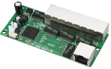
A network switch PCB is the core component of a network switch, responsible for managing data traffic between devices. It houses critical elements like microcontrollers, capacitors, resistors, and connectors that work together to ensure seamless communication. However, due to factors like electrical stress, heat, and physical damage, these boards can develop faults over time.
Common reasons for failure include power surges that damage components, overheating that weakens solder joints, and signal degradation that disrupts data transmission. Understanding these root causes is the first step in effective network switch PCB troubleshooting. Let's explore the most frequent issues and how to address them.
Common Issues in Network Switch PCBs
Before diving into repair techniques, it's important to recognize the typical problems that plague network switch PCBs. Here are the primary issues you might encounter:
1. Power Distribution Problems
Power distribution issues are a leading cause of network switch failures. These problems often manifest as intermittent power loss, device resets, or complete failure to power on. They can stem from faulty voltage regulators, damaged capacitors, or broken traces on the PCB.
For instance, a bulging or leaking electrolytic capacitor can disrupt the 3.3V or 5V rails commonly used in network switches, leading to unstable operation. Similarly, a cracked trace might prevent power from reaching critical components, causing the switch to malfunction.
2. Signal Integrity Issues
Signal integrity issues occur when data signals degrade or get distorted as they travel through the PCB. This can result in packet loss, slow network speeds, or dropped connections. Common causes include impedance mismatches, crosstalk between traces, or damaged Ethernet PHY chips.
In high-speed network switches, signal integrity is critical. For example, a 1 Gbps Ethernet signal requires precise impedance control (typically 100 ohms for differential pairs). Any deviation due to poor PCB layout or damaged components can lead to errors in data transmission.
3. Component Failure
Individual components on a network switch PCB, such as resistors, diodes, or integrated circuits (ICs), can fail due to electrical overstress, thermal damage, or manufacturing defects. A failed IC, for instance, might stop the switch from processing data, while a shorted diode could cause power issues.
Component failure often requires detailed analysis to pinpoint the faulty part. This process, known as component failure analysis, involves testing individual elements to identify the root cause of the problem.
Step-by-Step Guide to Network Switch PCB Troubleshooting
Now that we've covered the common issues, let's walk through a practical approach to troubleshooting and repairing a network switch PCB. Follow these steps to diagnose and resolve faults effectively.
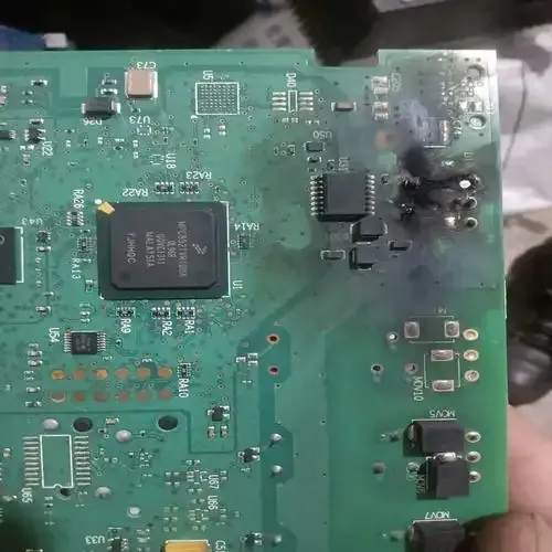
Step 1: Visual Inspection
Start with a thorough visual inspection of the PCB. Look for obvious signs of damage, such as burnt components, bulging capacitors, or cracked solder joints. Use a magnifying glass or a microscope if necessary to spot tiny cracks or corrosion on the board.
Pay close attention to areas near power input connectors, as these are often prone to stress from voltage spikes. If you notice a burnt smell or discoloration, it could indicate a short circuit or overheating issue.
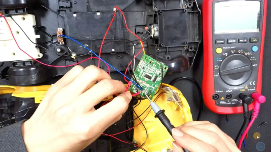
Step 2: Power Supply Testing
Since power distribution problems are a frequent issue, test the power supply next. Use a multimeter to check the voltage at key points on the PCB, such as the input pins of voltage regulators or the power rails (e.g., 3.3V and 5V lines). Compare the readings to the expected values listed in the switch's datasheet or schematic.
If the voltage is outside the acceptable range (e.g., below 3.0V on a 3.3V rail), inspect components like capacitors and regulators in the power circuit. Replace any faulty parts to restore proper power delivery.
Step 3: Signal Integrity Analysis
For signal integrity issues, use an oscilloscope to examine the data signals on the PCB. Focus on high-speed lines, such as those connected to Ethernet ports or internal data buses. Look for signs of noise, overshoot, or timing errors that could indicate impedance mismatches or crosstalk.
For example, if you're troubleshooting a Gigabit Ethernet switch, check the differential pairs for a clean square wave signal at approximately 125 MHz (the base frequency for 1 Gbps Ethernet). If the signal appears distorted, inspect the traces and nearby components for damage or poor soldering.
Step 4: Component Failure Analysis
If visual inspection and signal testing don't reveal the issue, perform a detailed component failure analysis. Use a multimeter in continuity mode to test for short circuits or open connections. For ICs and complex components, you might need a logic analyzer or specialized testing equipment to verify functionality.
Start with components in the suspected problem area. For instance, if a specific port on the switch isn't working, test the associated PHY chip and surrounding resistors or capacitors. Replace any defective parts with equivalents that match the original specifications.
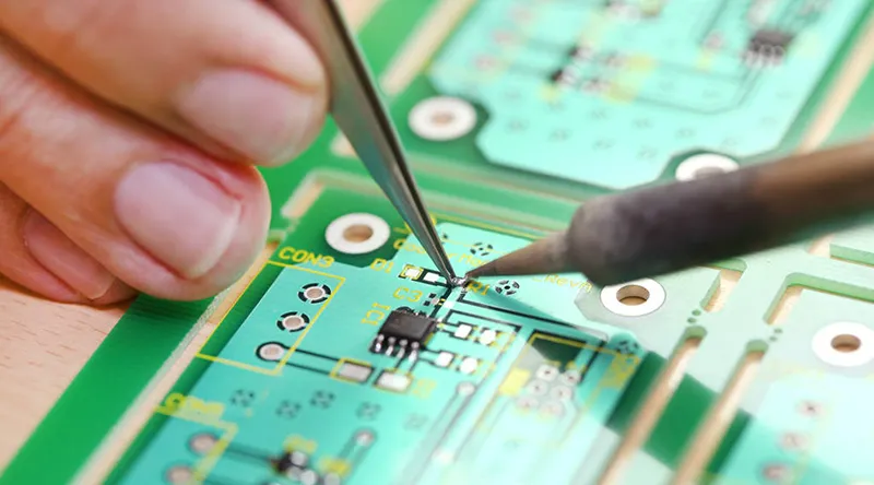
Step 5: PCB Repair Techniques
Once you've identified the fault, it's time for PCB repair. Depending on the issue, this could involve soldering a new component, repairing a broken trace, or cleaning corrosion from the board. Here are some practical tips:
- Replacing Components: Use a soldering iron with a fine tip (e.g., 1mm) and lead-free solder to replace damaged components. Ensure proper alignment and avoid overheating nearby parts.
- Trace Repair: For broken traces, use a conductive pen or thin wire to bridge the gap. Secure the repair with epoxy for durability.
- Cleaning: If corrosion is present, clean the area with isopropyl alcohol and a soft brush, then dry thoroughly before testing.
Preventing Future Issues in Network Switch PCBs
While troubleshooting and repair are essential skills, preventing problems in the first place is even better. Here are some tips to extend the lifespan of your network switch PCB:
1. Manage Heat: Ensure proper ventilation around the switch to prevent overheating. Use heat sinks or fans if the device operates in a high-temperature environment.
2. Protect Against Power Surges: Install surge protectors or uninterruptible power supplies (UPS) to shield the switch from voltage spikes that can cause power distribution problems.
3. Regular Maintenance: Periodically inspect the PCB for dust buildup or signs of wear. Clean the board and tighten connections to avoid intermittent faults.
4. Design Considerations: If you're involved in PCB design, prioritize robust layouts with proper grounding, adequate trace spacing, and high-quality components to minimize signal integrity issues.
Tools You’ll Need for Effective Troubleshooting
To tackle network switch PCB troubleshooting, having the right tools is crucial. Here's a list of essential equipment:
- Multimeter: For measuring voltage, current, and continuity.
- Oscilloscope: For analyzing signal integrity and waveform quality.
- Soldering Station: For repairing or replacing components.
- Magnifying Glass or Microscope: For detailed visual inspections.
- Logic Analyzer: For testing digital signals and IC functionality.
Investing in quality tools can save time and improve the accuracy of your diagnostics, making PCB repair more efficient.
Challenges in Troubleshooting and How to Overcome Them
Troubleshooting network switch PCBs can be complex, especially with densely packed boards or multilayer designs. Here are some challenges you might face and how to address them:
1. Identifying Hidden Faults: Faults in inner layers of a multilayer PCB are hard to detect. Use an X-ray inspection tool if available, or rely on schematic analysis to narrow down the problem area.
2. Lack of Documentation: Without a schematic or datasheet, troubleshooting becomes harder. Search for similar designs or use reverse engineering techniques to map out the circuit.
3. Delicate Components: Modern PCBs often have tiny surface-mount components that are easy to damage. Use anti-static wrist straps and precision tools to avoid accidental harm during repair.
Conclusion: Mastering Network Switch PCB Troubleshooting
Troubleshooting and repairing network switch PCBs doesn't have to be daunting. By following a systematic approach—starting with visual inspection, testing power and signals, performing component failure analysis, and applying effective PCB repair techniques—you can resolve common issues like power distribution problems and signal integrity issues with confidence.
Whether you're dealing with a failed capacitor, a broken trace, or signal distortion, the steps outlined in this guide provide a practical framework for network switch PCB troubleshooting. Equip yourself with the right tools, take preventive measures, and keep learning to handle even the most challenging faults.


