ALLPCB


If you're looking to build a basic radio receiver using a single-layer PCB, you're in the right place. A single-layer PCB, also known as a single-sided PCB, is an affordable and beginner-friendly option for creating simple electronics like a radio circuit. In this guide, we'll walk you through the process of designing and assembling a simple receiver PCB, perfect for a DIY radio project. Whether you're a hobbyist or a student learning about radio circuit PCBs, this step-by-step tutorial will help you create a functional device with minimal components and cost.
Below, we'll dive into the details of single-layer PCB design for radio circuits, the components you'll need, and how to build your very own simple receiver. Let's get started with everything you need to know about single-layer PCB electronics for radio projects.
What Is a Single-Layer PCB and Why Use It for Radio Circuits?
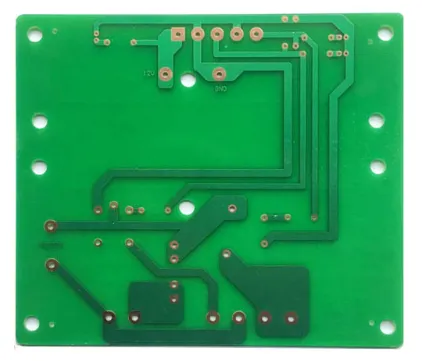
A single-layer PCB is a printed circuit board with conductive traces on only one side of the board. The other side is typically used for mounting components. These boards are the simplest type of PCB and are widely used in basic electronics due to their low cost and ease of manufacturing. For a DIY radio project, a single-layer PCB is ideal because it reduces complexity while still providing a stable platform for a simple receiver PCB design.
Radio circuits, especially basic AM or FM receivers, often require only a handful of components like transistors, capacitors, and inductors. A single-layer PCB can easily accommodate these components without the need for complex multilayer routing. Additionally, single-sided PCB electronics are perfect for beginners who want to experiment with radio circuit PCBs without investing in advanced tools or materials.
Benefits of Using Single-Layer PCB for a Simple Receiver
Before we dive into the design and assembly process, let's explore why a single-layer PCB is a great choice for building a simple receiver:
- Cost-Effective: Single-layer PCBs are the most affordable option for small-scale projects like a DIY radio.
- Easy to Design: With only one layer of traces, the layout process is straightforward, even for beginners using basic design software.
- Simple Manufacturing: These boards can be etched at home or ordered at a low cost from PCB fabrication services.
- Suitable for Basic Circuits: A simple receiver PCB doesn't require complex routing, making single-sided PCB electronics sufficient.
For a basic radio circuit PCB, these advantages make single-layer designs an excellent starting point. Now, let’s look at the components and tools you’ll need for your project.
Components and Tools for a Single-Layer PCB Radio Circuit
Building a simple receiver on a single-layer PCB requires minimal components. For this project, we’ll focus on creating a basic AM radio receiver, as it is one of the easiest circuits to design and build. Here’s what you’ll need:
Components
- Transistor: A general-purpose NPN transistor like the 2N2222 for amplification (1 piece).
- Variable Capacitor: A 365 pF tuning capacitor to adjust the frequency.
- Inductor/Coil: A handmade or purchased coil with an inductance of around 220 μH for tuning the AM band.
- Resistors: 1 kΩ and 10 kΩ resistors for biasing the transistor (1 each).
- Capacitors: 100 nF and 10 μF ceramic or electrolytic capacitors for filtering and coupling (1 each).
- Diode: A germanium diode (like 1N34A) for signal detection.
- Earphone or Small Speaker: For audio output (impedance around 8-32 ohms).
- Antenna Wire: A long wire (3-5 meters) to capture radio signals.
- Battery: A 9V battery or power source for the circuit.
- Single-Layer PCB: A small board (approximately 5x5 cm) for mounting components.
Tools
- Soldering iron and solder wire.
- PCB design software (free options are available online).
- Multimeter for testing connections.
- Wire cutters and strippers.
- Drill or etching kit if creating the PCB at home.
Designing the Single-Layer PCB for Your Radio Circuit
The first step in building your simple receiver PCB is designing the layout. Since this is a single-layer PCB, the design process is relatively simple. You’ll need to create a schematic and then convert it into a PCB layout with all traces on one side.
Step 1: Create the Schematic
The schematic for a basic AM radio receiver includes an antenna connected to a tuned circuit (inductor and variable capacitor in parallel), a detector (diode), and an amplifier (transistor stage). The output goes to an earphone or speaker. Use free design software to draw this schematic, ensuring all connections are clear.
For a typical AM receiver, the tuned circuit resonates at frequencies between 530 kHz and 1700 kHz (the AM broadcast band). The inductance (L) and capacitance (C) must satisfy the resonance formula: f = 1/(2π√(LC)). For example, with a 220 μH inductor and a 365 pF capacitor, you can tune to approximately 800 kHz at the midpoint.
Step 2: Convert to PCB Layout
Once the schematic is ready, convert it to a single-layer PCB layout. Place components on one side and route traces on the other. Keep traces short to minimize interference, especially around the tuned circuit. Ensure there’s enough space between components for easy soldering. For beginners, a 5x5 cm board should be sufficient for this simple receiver PCB.
Assembling Your Single-Layer PCB Radio Circuit
With your PCB designed and fabricated (or etched at home), it’s time to assemble the components. Follow these steps for a successful build:
Step 1: Prepare the PCB
If you’ve ordered a pre-fabricated board, ensure it’s clean and free of debris. If you etched it yourself, double-check for any broken traces or shorts using a multimeter. Drill holes if necessary for through-hole components.
Step 2: Solder the Components
Start by soldering the smallest components like resistors and capacitors. Then, add the transistor and diode, paying attention to their orientation (check the datasheet for pinouts). Finally, attach the variable capacitor, inductor, and external connections like the antenna and earphone. Use minimal solder to avoid bridges on this single-sided PCB electronics project.
Step 3: Connect Power and Test
Attach the 9V battery or power source. Connect the antenna wire (extend it as long as possible for better reception). Turn on the circuit and adjust the variable capacitor to tune into an AM station. You should hear faint audio through the earphone. If there’s no sound, check your connections and ensure the tuned circuit is working (test resonance with a multimeter if needed).
Troubleshooting Tips for Your Single-Layer PCB Radio
If your simple receiver PCB doesn’t work as expected, don’t worry. Here are some common issues and solutions:
- No Sound: Check the antenna connection and ensure it’s long enough (3-5 meters). Verify the transistor and diode orientations.
- Weak Signal: Adjust the inductor or capacitor values to better match the AM band (530-1700 kHz). Move to an area with better reception.
- Static or Noise: Shorten PCB traces if possible, as long traces can pick up interference. Ensure all solder joints are clean.
Enhancing Your DIY Radio Project
Once your basic single-layer PCB radio circuit is working, you can take it to the next level with these upgrades:
- Add an Amplifier: Use an additional transistor stage or a small audio amplifier IC to boost the output for a louder speaker.
- Switch to FM: Redesign the tuned circuit for the FM band (88-108 MHz) using a smaller inductor (around 0.1 μH) and capacitor (10-50 pF).
- Enclosure: Build a small box to house the PCB and components, protecting them and improving portability.
Why Choose Professional PCB Services for Your Radio Circuit?
While etching a single-layer PCB at home is possible, ordering from a professional PCB fabrication service offers several advantages, especially for beginners. Professional services ensure precise traces, consistent quality, and durability, which are crucial for a reliable radio circuit PCB. Additionally, you can order multiple copies of your simple receiver PCB for future projects or to share with friends.
At ALLPCB, we specialize in providing high-quality single-layer PCBs at competitive prices. Our user-friendly platform allows you to upload your design, review it, and have your boards delivered quickly. Whether it’s for a DIY radio project or other single-sided PCB electronics, we’re here to support your creativity with fast turnaround times and excellent customer service.
Conclusion: Start Building Your Single-Layer PCB Radio Today
Building a simple receiver using a single-layer PCB is an exciting and rewarding DIY radio project. With just a few components and a well-designed radio circuit PCB, you can tune into AM stations and learn the basics of electronics. Single-sided PCB electronics are perfect for beginners due to their simplicity and affordability, making them an excellent choice for experimenting with basic radio circuits.
Follow the steps outlined in this guide to design, assemble, and troubleshoot your own simple receiver PCB. Whether you’re a hobbyist or a student, this project will give you hands-on experience with single-layer PCB radio design. Order your PCB today and take the first step toward creating your very own radio receiver!