 ALLPCB


In the fast-evolving world of electronics, where devices are shrinking and designs are becoming more complex, rigid-flex printed circuit boards (PCBs) have emerged as a game-changer. These hybrid boards combine the structural stability of rigid PCBs with the adaptability of flexible circuits, enabling engineers to create compact, reliable, and innovative products. From wearable devices to aerospace systems, rigid-flex PCBs are redefining what's possible in electronic design. In this blog, we explore the technology behind rigid-flex PCBs, their advantages, design challenges, and practical applications, providing engineers with actionable insights to leverage this versatile solution.
What Are Rigid-Flex PCBs?
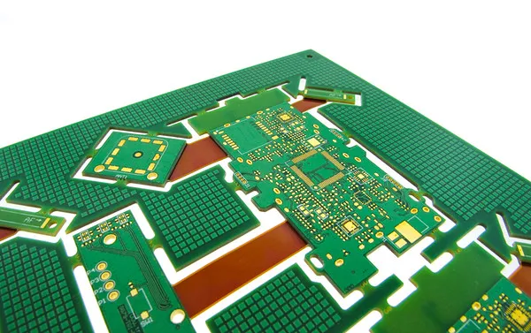
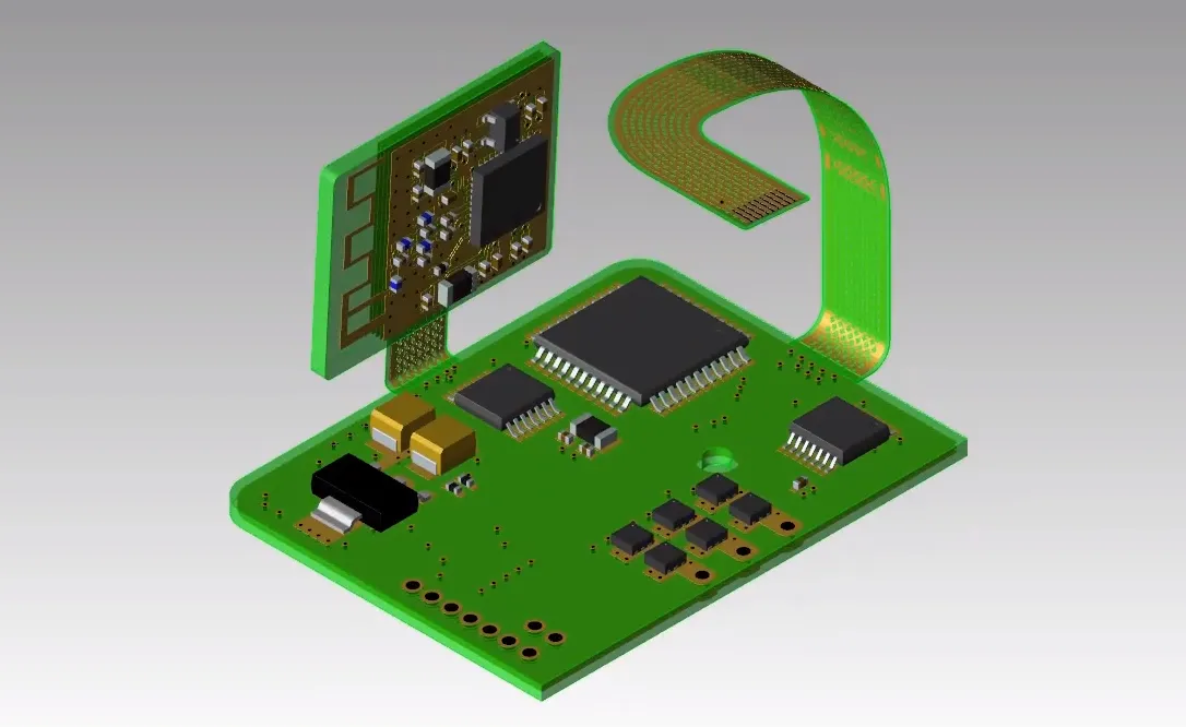
Rigid-flex PCBs are hybrid circuit boards that integrate rigid and flexible substrates into a single unit. The rigid sections, typically made from FR4 or similar materials, provide mechanical support for components and connectors. The flexible sections, often crafted from polyimide films, allow the board to bend, fold, or twist to fit into tight or irregular spaces. These boards are interconnected without external cables, reducing points of failure and enhancing reliability.
Unlike traditional rigid PCBs, which are inflexible, or fully flexible PCBs, which lack structural rigidity, rigid-flex PCBs offer the best of both worlds. They are designed to withstand mechanical stress, vibrations, and thermal expansion while maintaining electrical performance. For example, a typical rigid-flex PCB might feature a 4-layer stackup with two rigid FR4 layers and two flexible polyimide layers, bonded using epoxy pre-preg films for durability.
Key Advantages of Rigid-Flex PCBs
Rigid-flex PCBs offer a unique combination of benefits that make them ideal for demanding applications. Here are the primary advantages:
Space Efficiency and Miniaturization
Rigid-flex PCBs eliminate the need for bulky connectors and cables, allowing engineers to design compact devices. By folding or bending the flexible sections, a rigid-flex PCB can fit into spaces where rigid boards would be impractical. For instance, in a smartphone, a rigid-flex PCB can wrap around components, reducing the device's footprint by up to 50% compared to rigid PCB assemblies.
Enhanced Reliability
The integrated design of rigid-flex PCBs reduces the number of interconnects, such as solder joints and connectors, which are common failure points. This leads to improved signal integrity and lower risks of connection failures. In high-vibration environments, such as automotive or aerospace applications, rigid-flex PCBs can achieve a mean time between failures (MTBF) of over 100,000 hours.
Durability Under Stress
The flexible polyimide layers in rigid-flex PCBs can withstand repeated bending (up to 500,000 flex cycles in dynamic applications) and mechanical shocks. Combined with the rigidity of FR4 sections, these boards resist vibrations and impacts, making them suitable for rugged applications like military missile guidance systems.
Weight Reduction
By replacing cables and connectors with lightweight polyimide films, rigid-flex PCBs significantly reduce system weight. In aerospace applications, where every gram matters, rigid-flex designs can reduce weight by 20-30% compared to traditional rigid PCB assemblies.
Thermal Stability
Polyimide materials used in flexible layers offer excellent thermal stability, withstanding temperatures up to 400°C. This makes rigid-flex PCBs ideal for high-temperature environments, such as automotive engine control units, where heat dissipation is critical.
Design Challenges and Solutions
While rigid-flex PCBs offer significant advantages, they come with unique design challenges that require careful planning and expertise. Below, we outline the key challenges and practical solutions.
Bend Radius Considerations
The flexible sections of a rigid-flex PCB must adhere to minimum bend radius requirements to prevent cracking or delamination. For a single-layer flex circuit, the bend radius should be at least 6 times the thickness of the flex layer (e.g., 0.6 mm for a 0.1 mm thick layer). In dynamic flex applications, a larger radius (10-12 times the thickness) is recommended.
Solution: Use PCB design software like Altium Designer to simulate bending and ensure compliance with IPC-2223 guidelines. Rasterize ground planes in flex areas to reduce stress and prevent copper fracturing.
Material Selection
Choosing the right materials is critical for balancing flexibility, durability, and electrical performance. Polyimide is the standard for flexible layers due to its low dielectric constant (Dk ≈ 3.4), which supports high-speed signal transmission (up to 10 Gbps for USB3.1 Gen.2). However, polyimide's high moisture absorption can affect performance if not properly managed.
Solution: Select rolled annealed copper foil for flexible layers to enhance flex cycle durability. Dry polyimide-based boards at 120°C for 4 hours before assembly to mitigate moisture issues.
Signal Integrity
Maintaining signal integrity in rigid-flex PCBs is challenging due to the transition between rigid and flexible layers, which can introduce impedance mismatches. For high-speed applications, differential pairs must maintain a characteristic impedance of 90 ohms.
Solution: Use controlled impedance design techniques, such as adjusting trace widths and spacing (e.g., 0.1 mm trace width for a 75 µm polyimide core). Employ shielding techniques, like grounded copper planes, to minimize electromagnetic interference (EMI).
Thermal Management
High-current applications, such as power electronics, can cause thermal expansion in rigid-flex PCBs, leading to mechanical stress. Flexible sections may stretch, while rigid sections remain stable, risking fatigue over time.
Solution: Incorporate thermal vias and heat sinks in rigid sections to dissipate heat efficiently. For example, a 12-layer rigid-flex PCB with a heat sink can maintain operating temperatures below 85°C in high-power applications.
Applications of Rigid-Flex PCBs
Rigid-flex PCBs are transforming industries by enabling innovative designs and reliable performance. Here are some key applications:
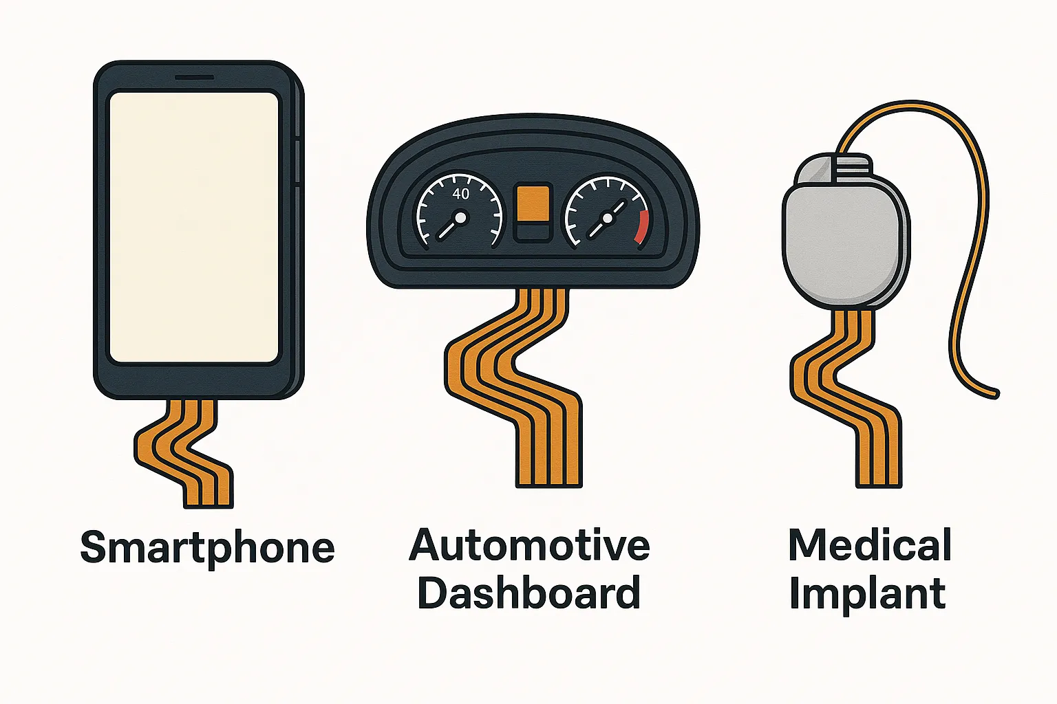
Consumer Electronics
Smartphones, laptops, and wearable devices rely on rigid-flex PCBs for their compact size and flexibility. For example, a smartwatch may use a 6-layer rigid-flex PCB to integrate sensors, displays, and batteries in a curved form factor.
Medical Devices
In medical imaging equipment and implantable devices like pacemakers, rigid-flex PCBs provide reliability and miniaturization. Their ability to conform to complex geometries ensures seamless integration into small, biocompatible housings.
Automotive Systems
Rigid-flex PCBs are used in advanced driver-assistance systems (ADAS) and infotainment systems, where they withstand vibrations and high temperatures. A typical automotive rigid-flex PCB might feature an 8-layer PCB design with ENIG (Electroless Nickel Immersion Gold) finish for corrosion resistance.
Aerospace and Defense
In satellites, avionics, and missile guidance systems, rigid-flex PCBs offer lightweight, durable solutions for harsh environments. Their ability to survive high-shock loads (up to 100G) makes them ideal for military applications.
Industrial Robotics
Robotic arms and machinery with moving parts benefit from rigid-flex PCBs' flexibility and durability. These boards enable compact connections in automated systems, improving efficiency and reducing maintenance.
Best Practices for Rigid-Flex PCB Design
To maximize the performance of rigid-flex PCBs, engineers should follow these best practices:
1. Limit Flex Layers: Use 1-2 flex layers for optimal flexibility and cost savings. Additional layers increase complexity and manufacturing costs.
2. Symmetrical Stackup: Design a symmetrical layer stackup to minimize warping. For example, a 4-layer PCB should have equal rigid and flex layers on both sides of the neutral axis.
3. Teardrop Pads: Use teardrop-shaped connections between traces and solder pads to reduce stress concentrations and improve reliability.
4. Stiffeners: Add polyimide or FR4 stiffeners in areas requiring mechanical support, such as connector regions, to achieve thicknesses of 0.2-1 mm.
5. Testing and Validation: Perform rigorous design verification, including electrical rule checking (ERC) and design rule checking (DRC), to ensure manufacturability. Conduct flex cycle testing to validate durability.
How ALLPCB Supports Rigid-Flex PCB Innovation
For engineers looking to bring rigid-flex PCB designs to life, partnering with a reliable manufacturer is crucial. ALLPCB offers advanced manufacturing capabilities, quick-turn prototyping, and global logistics to streamline the development process. Our state-of-the-art facilities support complex multilayer rigid-flex designs, with options for ENIG, OSP, and HASL surface finishes to meet diverse application needs. With turnaround times as fast as 24 hours and comprehensive design-for-manufacturability (DFM) support, we empower engineers to iterate quickly and achieve high-quality results, whether for consumer electronics, medical devices, or aerospace systems.
Conclusion
Rigid-flex PCBs represent a powerful solution for modern electronic design, combining durability, flexibility, and space efficiency. By addressing design challenges like bend radius, material selection, and signal integrity, engineers can unlock the full potential of this technology across industries. From consumer gadgets to critical aerospace systems, rigid-flex PCBs enable innovation without compromising reliability. By following best practices and leveraging advanced manufacturing support, designers can create cutting-edge products that meet the demands of today's dynamic market.


