 ALLPCB


In the world of medical imaging, MRI systems demand cutting-edge technology to ensure precision, reliability, and patient safety. One critical component in these systems is the printed circuit board (PCB), specifically rigid-flex PCBs. These hybrid boards combine the durability of rigid PCBs with the adaptability of flexible circuits, making them ideal for the compact and complex designs of MRI machines. If you're looking to understand how rigid-flex PCBs enhance MRI systems or seeking guidance on design and manufacturing for high-reliability applications, you've come to the right place. This blog dives deep into the role of rigid-flex PCBs in MRI technology, covering design rules, stackup considerations, and manufacturing insights.
What Are Rigid-Flex PCBs and Why Are They Essential for MRI Systems?
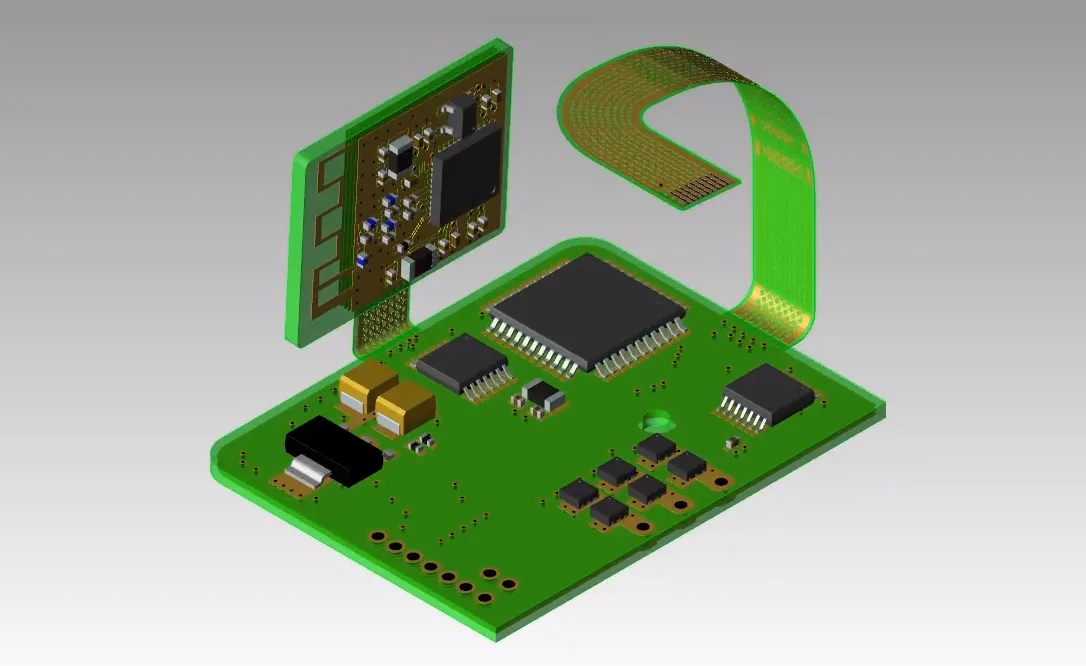
Rigid-flex PCBs are a unique type of circuit board that integrates rigid sections for structural stability with flexible sections for bending and movement. This combination is particularly valuable in MRI systems, where space is limited, and components must withstand constant vibrations and electromagnetic interference (EMI). The durability of rigid areas supports heavy components like connectors, while the flexibility allows the board to fit into tight or curved spaces within the MRI machine.
MRI systems rely on precise signal transmission to generate detailed images of the human body. A rigid-flex PCB for MRI ensures minimal signal loss and high reliability, even under demanding conditions. These boards also reduce the need for multiple connectors and cables, lowering the risk of failure points and enhancing overall system performance. For engineers designing MRI equipment, using rigid-flex technology can mean the difference between a reliable system and one prone to costly downtime.
Key Benefits of Rigid-Flex PCBs in MRI Applications
The use of rigid-flex PCBs in MRI systems offers several advantages that directly impact performance and reliability. Here are some of the standout benefits:
- Space Efficiency: MRI machines are compact, with intricate internal layouts. Rigid-flex PCBs can bend and fold to fit into tight spaces, reducing the overall footprint of the electronics.
- Enhanced Durability: The rigid sections provide mechanical strength to support components, while the flexible parts endure repeated bending without breaking—crucial for MRI systems that experience vibrations during operation.
- Improved Signal Integrity: With fewer connectors and shorter signal paths, rigid-flex PCBs minimize signal loss and EMI, ensuring accurate data transmission for high-quality imaging.
- High Reliability: A high-reliability MRI PCB reduces the risk of failure in critical medical applications, where downtime can affect patient care and operational costs.
These benefits make rigid-flex PCBs a go-to choice for MRI manufacturers aiming to balance performance with practicality in their designs.
Understanding MRI PCB Stackup for Optimal Performance
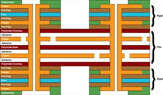
The stackup of a PCB refers to the arrangement of conductive and insulating layers within the board. For MRI systems, designing an effective MRI PCB stackup is vital to ensure signal integrity, manage EMI, and maintain structural stability. A typical rigid-flex PCB stackup for MRI applications might include multiple layers, each serving a specific purpose.
For instance, a common stackup could consist of 6 to 8 layers, with rigid sections having a standard FR4 material for stability and flexible sections using polyimide for bendability. Signal layers are often sandwiched between ground planes to shield against EMI—a critical concern in MRI systems where electromagnetic fields are intense. Impedance control is also key; maintaining a consistent impedance of 50 ohms for high-speed signals ensures minimal reflection and signal distortion.
Here’s a simplified example of an MRI PCB stackup:
- Top Layer: Signal routing for high-speed data (rigid section)
- Layer 2: Ground plane for EMI shielding
- Layer 3: Power distribution
- Layer 4: Flexible signal layer (polyimide)
- Layer 5: Ground plane (flexible)
- Bottom Layer: Additional signal routing (rigid section)
Designing the stackup requires balancing the number of layers with cost and manufacturability while meeting the stringent requirements of MRI systems. Engineers must also consider thermal management, as MRI components can generate significant heat during operation. Adding thermal vias or using materials with high thermal conductivity can help dissipate heat effectively.
Rigid-Flex PCB Design Rules for MRI Systems
Designing a rigid-flex PCB for MRI systems involves adhering to specific rigid-flex PCB design rules to ensure functionality and reliability. These rules address the unique challenges of combining rigid and flexible materials while meeting the strict standards of medical equipment. Below are some essential guidelines:
1. Bend Radius Considerations
The flexible sections of a rigid-flex PCB must be designed with an appropriate bend radius to prevent cracking or delamination. A general rule is to maintain a bend radius of at least 10 times the thickness of the flexible material. For example, if the flexible layer is 0.1 mm thick, the bend radius should be at least 1 mm. Tighter bends can lead to mechanical stress and failure over time, especially in MRI systems with frequent vibrations.
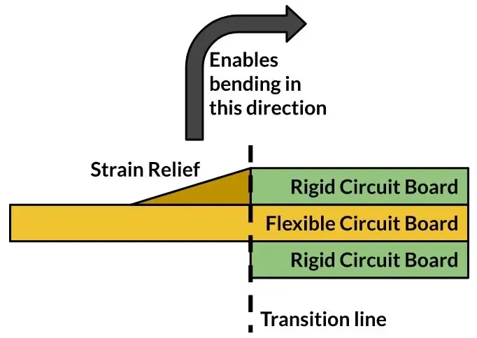
2. Transition Zones
The area where rigid and flexible sections meet, known as the transition zone, is prone to stress. Designers should avoid placing vias or critical traces in this area to prevent damage. Reinforcing the transition zone with additional material or staggered layers can also improve durability.
3. Material Selection
Choosing the right materials is crucial for a high-reliability MRI PCB. Rigid sections often use FR4 or high-Tg materials to handle mechanical stress, while flexible sections rely on polyimide for its excellent thermal and mechanical properties. Copper foil thickness should be optimized—typically 1 oz (35 μm) for signal layers—to balance flexibility and conductivity.
4. EMI Shielding
MRI systems operate in environments with strong electromagnetic fields, so shielding is non-negotiable. Incorporate ground planes and ensure proper grounding in the design. Keep high-speed signal traces short and route them away from noisy areas to minimize interference.
5. Component Placement
Place heavier components on rigid sections to avoid stressing the flexible areas. Also, ensure that components near bend areas have enough clearance to prevent mechanical interference during flexing.
Following these rigid-flex PCB design rules helps create boards that meet the demanding requirements of MRI systems, ensuring long-term reliability and performance.
Rigid-Flex PCB Manufacturing for MRI Systems
The manufacturing process for rigid-flex PCBs is more complex than for traditional rigid boards due to the combination of materials and the need for precision. When it comes to rigid-flex PCB manufacturing for MRI systems, several factors must be considered to achieve high reliability and performance.
1. Material Bonding
During manufacturing, rigid and flexible layers are bonded together using adhesives or lamination processes. The bonding must be uniform to prevent delamination, especially in the high-stress environment of an MRI machine. Manufacturers often use no-flow prepreg materials to ensure a strong bond without excess resin flow that could affect flexibility.
2. Precision Drilling and Cutting
Drilling vias and cutting the board outline require high precision to avoid damaging the flexible sections. Laser drilling is often used for microvias in flexible areas, as it provides greater accuracy and reduces mechanical stress compared to traditional drilling methods.
3. Quality Testing
High-reliability MRI PCBs undergo rigorous testing to ensure they meet medical standards. This includes electrical testing for continuity and insulation resistance, as well as mechanical testing to verify the board’s ability to withstand bending cycles. For MRI applications, boards may also be tested for EMI performance to ensure they don’t interfere with imaging accuracy.
4. Surface Finish
The surface finish of a rigid-flex PCB impacts its solderability and long-term reliability. Electroless Nickel Immersion Gold (ENIG) is a common choice for MRI PCBs due to its excellent corrosion resistance and flat surface, which ensures reliable soldering of fine-pitch components.
Partnering with an experienced manufacturer is essential for producing rigid-flex PCBs that meet the strict demands of MRI systems. The right manufacturer will have the expertise and equipment to handle the complexities of rigid-flex technology, ensuring consistent quality and performance.
Challenges in Using Rigid-Flex PCBs for MRI Systems
While rigid-flex PCBs offer numerous advantages, they also come with challenges that engineers must address during design and manufacturing. Understanding these challenges can help in creating more robust solutions for MRI applications.
- Cost: Rigid-flex PCBs are more expensive to design and manufacture compared to standard rigid boards due to their complexity and specialized materials. However, the long-term reliability and space savings often justify the initial investment in critical applications like MRI systems.
- Design Complexity: Combining rigid and flexible sections requires careful planning to avoid stress points and ensure signal integrity. Engineers must invest time in simulation and prototyping to validate designs before production.
- Thermal Management: MRI systems generate heat, and rigid-flex PCBs must dissipate it effectively to prevent component failure. Incorporating thermal vias and selecting materials with good thermal conductivity are essential steps.
By anticipating these challenges and addressing them early in the design process, engineers can maximize the benefits of rigid-flex technology in MRI systems.
How Rigid-Flex PCBs Ensure High-Reliability in MRI Systems
A high-reliability MRI PCB is non-negotiable in medical imaging, where equipment failure can have serious consequences. Rigid-flex PCBs contribute to reliability in several ways. First, their integrated design reduces the number of connectors and solder joints, which are common failure points in traditional PCB assemblies. Fewer connections mean a lower risk of disconnection or signal loss over time.
Second, the materials used in rigid-flex PCBs, such as polyimide for flexible sections, offer excellent resistance to temperature fluctuations and mechanical stress. This durability ensures that the PCB can withstand the harsh operating conditions of an MRI machine, including vibrations and strong magnetic fields.
Finally, rigid-flex PCBs enable more compact and streamlined designs, reducing the overall weight and complexity of the system. This simplicity translates to easier maintenance and fewer opportunities for errors during assembly or operation.
Conclusion: The Future of Rigid-Flex PCBs in MRI Technology
Rigid-flex PCBs are a game-changer for MRI systems, offering the perfect blend of durability and flexibility needed for cutting-edge medical imaging. By adhering to rigid-flex PCB design rules, optimizing MRI PCB stackup, and leveraging advanced rigid-flex PCB manufacturing techniques, engineers can create high-reliability MRI PCBs that meet the stringent demands of the healthcare industry.
As MRI technology continues to evolve, the role of rigid-flex PCBs will only grow. Their ability to save space, improve signal integrity, and withstand challenging environments makes them indispensable for next-generation medical devices. Whether you're an engineer designing MRI equipment or a manufacturer looking to enhance your product offerings, understanding the benefits and best practices of rigid-flex PCBs is the key to staying ahead in this critical field.
At ALLPCB, we’re committed to supporting innovation in medical technology with high-quality PCB solutions tailored to your needs. Explore how rigid-flex technology can elevate your MRI systems and ensure unmatched reliability for years to come.


