 ALLPCB


In the fast-paced world of mobile phone technology, high-frequency applications demand materials that ensure optimal performance with minimal signal loss. For engineers and designers, choosing the right PCB (Printed Circuit Board) material is critical. This blog dives into a comparative analysis of high-frequency PCB materials, focusing on popular options like Rogers PCB and PTFE PCB. We'll explore key factors such as dielectric loss and signal attenuation to help you make informed decisions for mobile phone applications.
Whether you're designing 5G components or high-speed data systems, understanding how these materials perform under high-frequency conditions can make all the difference. Let’s break down the essentials and provide a detailed guide to selecting the best material for your needs, with a focus on long-tail keywords like high-frequency PCB materials, Rogers PCB, PTFE PCB, dielectric loss, and signal attenuation.
Why High-Frequency PCB Materials Matter in Mobile Phones
Mobile phones today operate at incredibly high frequencies, especially with the rise of 5G technology, which can range from 600 MHz to over 40 GHz in some bands. At these frequencies, signal integrity becomes a challenge. Standard PCB materials like FR-4 often fall short due to higher dielectric loss and poor signal transmission. This is where specialized high-frequency PCB materials come into play.
High-frequency PCB materials are designed to minimize signal attenuation (the loss of signal strength) and dielectric loss (energy dissipation in the material). These properties ensure that data travels quickly and reliably across the board, which is essential for mobile phone applications like antennas, RF (radio frequency) modules, and high-speed data processing circuits.
In this blog, we’ll compare two leading material types used in high-frequency applications for mobile phones, focusing on their performance metrics and suitability.
Understanding Key Performance Factors: Dielectric Loss and Signal Attenuation
Before diving into specific materials, let’s clarify the two critical factors that define high-frequency PCB performance: dielectric loss and signal attenuation.
- Dielectric Loss (Dissipation Factor, Df): This measures how much energy a material loses as heat when an electric field passes through it. A lower dielectric loss means less energy is wasted, which is crucial for maintaining signal quality in high-frequency applications. Materials with a dissipation factor below 0.005 are often preferred for mobile phone PCBs operating at GHz frequencies.
- Signal Attenuation: This refers to the reduction in signal strength as it travels through the PCB. Attenuation is influenced by the material’s dielectric constant (Dk), which affects signal speed, and the material’s loss tangent. Lower attenuation ensures clearer, faster data transmission, which is vital for 5G and other high-speed mobile technologies.
With these factors in mind, let’s compare two prominent high-frequency PCB materials used in mobile phone applications.
Rogers PCB: A Leader in High-Frequency Performance
Rogers PCB materials are widely recognized in the industry for their excellent performance in high-frequency environments. These materials are often based on ceramic-filled composites, which provide a stable dielectric constant and low dielectric loss, making them ideal for mobile phone applications.
Key Features of Rogers PCB Materials
- Low Dielectric Loss: Many Rogers materials have a dissipation factor as low as 0.0013 at 10 GHz, ensuring minimal energy loss even at high frequencies used in 5G networks.
- Stable Dielectric Constant (Dk): With Dk values typically ranging from 2.2 to 10.2, Rogers materials offer consistent signal speeds, reducing the risk of signal distortion in mobile phone RF modules.
- Thermal Stability: These materials maintain performance across a wide temperature range, which is crucial for mobile devices that may heat up during operation.
- Applications in Mobile Phones: Rogers materials are often used in antennas, power amplifiers, and filters within mobile devices due to their ability to handle frequencies up to 40 GHz with low signal attenuation.
While Rogers PCB materials excel in performance, they can be more expensive than traditional options. However, for high-frequency applications where signal integrity is non-negotiable, the investment often pays off.
PTFE PCB: A Reliable Choice for High-Frequency Designs
PTFE (Polytetrafluoroethylene) PCB materials, often referred to as Teflon-based materials, are another popular choice for high-frequency applications. Known for their low dielectric constant and excellent chemical resistance, PTFE PCBs are widely used in mobile phone designs that require reliable signal transmission.
Key Features of PTFE PCB Materials
- Ultra-Low Dielectric Loss: PTFE materials often have a dissipation factor of around 0.0009 at 10 GHz, making them one of the best options for minimizing energy loss in high-frequency circuits.
- Low Dielectric Constant (Dk): With a Dk typically around 2.1, PTFE ensures faster signal propagation, which is ideal for high-speed data transfer in mobile phones.
- High Thermal and Chemical Resistance: PTFE materials withstand harsh conditions, ensuring durability in compact mobile phone designs where space and heat management are challenges.
- Applications in Mobile Phones: PTFE is commonly used in RF and microwave circuits, including base station components and mobile phone antennas, due to its low signal attenuation properties.
One downside of PTFE PCB materials is their softer nature, which can make them trickier to process during manufacturing. Despite this, their performance in high-frequency environments often outweighs the challenges for mobile phone applications.
Comparative Analysis: Rogers PCB vs. PTFE PCB
Now that we’ve covered the individual strengths of Rogers PCB and PTFE PCB materials, let’s compare them head-to-head across key metrics relevant to high-frequency mobile phone applications.
| Criteria | Rogers PCB | PTFE PCB |
|---|---|---|
| Dielectric Constant (Dk) | 2.2 - 10.2 (varies by specific material) | ~2.1 |
| Dissipation Factor (Df at 10 GHz) | ~0.0013 | ~0.0009 |
| Signal Attenuation | Low, suitable for up to 40 GHz | Very low, excellent for microwave frequencies |
| Thermal Stability | High, ideal for mobile device heat | Very high, withstands extreme conditions |
| Manufacturing Ease | Easier to process than PTFE | Softer material, can be challenging |
| Cost | Higher than standard materials | Often more expensive due to processing |
Which Material Wins for Mobile Phone Applications?
Both Rogers PCB and PTFE PCB materials excel in high-frequency environments, but the choice depends on your specific mobile phone application. If you’re working on a design that requires a wide range of dielectric constants and easier manufacturing, Rogers materials might be the better fit. For applications where the lowest possible dielectric loss and signal attenuation are critical, such as in microwave-frequency antennas, PTFE could be the superior choice.
In many cases, hybrid designs using both materials in different layers of a multilayer PCB can offer the best of both worlds, balancing cost, performance, and manufacturability.
Other Considerations for High-Frequency PCB Materials in Mobile Phones
Beyond material choice, several other factors influence the performance of high-frequency PCB materials in mobile phone applications:
- Board Thickness: Thinner boards reduce signal travel distance, minimizing attenuation. However, they must still provide structural integrity for compact mobile designs.
- Copper Foil Quality: High-frequency signals are sensitive to surface roughness. Using low-profile copper foils can reduce signal loss.
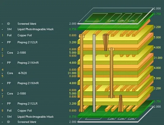
- Layer Stack-Up Design: Proper impedance matching in multilayer designs prevents signal reflection, ensuring smooth data transmission at frequencies above 1 GHz.
By considering these elements alongside material selection, you can optimize your PCB design for the demanding requirements of modern mobile phones.
How to Choose the Right High-Frequency PCB Material for Your Mobile Phone Project
Selecting the best material for your mobile phone PCB involves balancing performance, cost, and design constraints. Here are some practical steps to guide your decision:
- Define Frequency Requirements: Determine the operating frequency of your application. For 5G components above 20 GHz, prioritize materials with the lowest dielectric loss and signal attenuation.
- Evaluate Thermal Needs: Consider the heat dissipation requirements of your mobile device. Both Rogers and PTFE materials offer strong thermal stability, but ensure the chosen material matches your operating environment.
- Assess Manufacturing Capabilities: Check if your production process can handle the material’s properties, especially for softer materials like PTFE.
- Budget Considerations: While high-frequency PCB materials cost more than standard options, weigh the performance benefits against your project budget.
By following these steps, you can narrow down your options and select a material that ensures reliable performance for your mobile phone application.
Future Trends in High-Frequency PCB Materials for Mobile Phones
As mobile technology evolves, so do the materials used in PCB manufacturing. The rollout of 5G and upcoming 6G technologies will push the boundaries of frequency ranges, demanding even lower dielectric loss and signal attenuation. Researchers are exploring advanced composites and hybrid materials that combine the benefits of Rogers and PTFE with improved cost-efficiency.
Additionally, sustainability is becoming a focus, with efforts to develop eco-friendly high-frequency PCB materials that maintain performance while reducing environmental impact. Staying updated on these trends can help engineers prepare for the next generation of mobile phone designs.

Conclusion: Making the Right Choice for High-Frequency Mobile Phone PCBs
Choosing the right high-frequency PCB material is a critical step in designing mobile phones that meet today’s performance demands. Both Rogers PCB and PTFE PCB materials offer exceptional properties for minimizing dielectric loss and signal attenuation, making them top choices for applications like 5G antennas and RF modules.
By understanding the strengths of each material and aligning them with your project’s specific requirements, you can ensure optimal signal integrity and reliability. Whether you prioritize ease of manufacturing with Rogers materials or the ultra-low loss of PTFE, the right choice will enhance your mobile phone’s performance in high-frequency environments.
At ALLPCB, we’re committed to supporting engineers with high-quality materials and manufacturing solutions tailored for high-frequency applications. Explore our offerings to find the perfect fit for your next mobile phone PCB project.


