 ALLPCB


If you're looking to understand the PCB manufacturing process for aircraft cockpit displays, you're in the right place. This guide walks you through every stage of aerospace PCB fabrication, from initial design to final quality checks, ensuring precision and reliability for critical aviation applications. Whether you're an engineer or a project manager in the aerospace sector, you'll find actionable insights on surface mount assembly, through-hole assembly, and PCB quality control to help you navigate this complex process.
In the sections below, we dive deep into each step, breaking down technical aspects with clear explanations and practical details. Let's explore how these vital components are brought to life for the high-stakes environment of aircraft cockpits.
Why Aircraft Cockpit Display PCBs Demand Precision
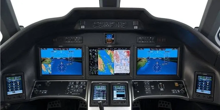
Aircraft cockpit displays are the heart of a pilot's interaction with the aircraft, providing critical data like altitude, speed, and navigation. The printed circuit boards (PCBs) behind these displays must meet stringent standards due to the harsh conditions of flight—extreme temperatures, vibrations, and electromagnetic interference (EMI). A single failure in a PCB can compromise safety, making precision in design and manufacturing non-negotiable.
In aerospace, PCBs often need to handle high-frequency signals for real-time data processing, with impedance values typically controlled within ±10% of the target (e.g., 50 ohms for many high-speed designs). This level of accuracy ensures signal integrity, which is vital for displays that update every millisecond. With this in mind, let’s break down the journey from design to a fully functional PCB.
Step 1: Designing PCBs for Aerospace Applications
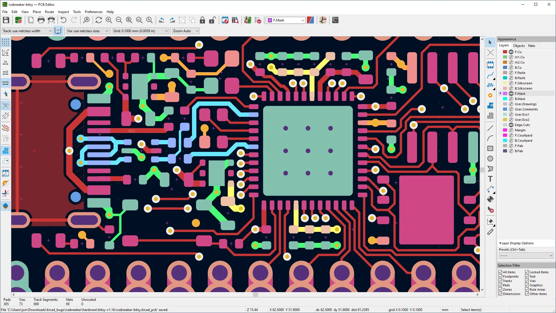
The first step in the PCB manufacturing process for cockpit displays is creating a detailed design. Engineers use specialized software to draft layouts that account for the unique demands of aerospace environments. This includes selecting materials like high-temperature laminates (e.g., FR-4 with enhanced thermal stability or polyimide) that can withstand temperatures ranging from -55°C to 125°C, common in flight conditions.
Key considerations during design include:
- Layer Stackup: Cockpit display PCBs often use multi-layer designs (8-16 layers or more) to accommodate complex circuitry while minimizing size. This helps manage high-density interconnects for compact displays.
- Signal Integrity: High-speed signals, often operating at frequencies above 1 GHz, require careful trace routing to avoid crosstalk and maintain signal speeds.
- EMI Shielding: Designs incorporate ground planes and shielding to reduce interference from nearby avionics systems.
Once the schematic and layout are finalized, the design files are prepared for fabrication, ensuring every specification aligns with aerospace standards like IPC-6012 Class 3 for high-reliability electronics.
Step 2: Material Selection in Aerospace PCB Fabrication
Material choice is a cornerstone of aerospace PCB fabrication. Standard consumer-grade materials won't cut it in the demanding conditions of flight. For cockpit display PCBs, manufacturers often opt for:
- High-Tg FR-4: With a glass transition temperature (Tg) above 170°C, this material resists thermal stress during rapid altitude changes.
- Polyimide: Known for flexibility and thermal resistance, polyimide is ideal for rigid-flex PCBs used in compact cockpit setups.
- Copper Thickness: Heavier copper layers (2-3 oz/ft2) are used to handle higher currents and improve heat dissipation.
Dielectric thickness is also critical. As noted in industry guidelines, a minimum dielectric thickness of 3.5 mil ensures mechanical strength under vibration and stress, a must for aviation applications. These materials are chosen not just for performance but also for compliance with standards like MIL-PRF-31032, which governs military and aerospace electronics.
Step 3: Fabrication Process for Cockpit Display PCBs
The PCB manufacturing process transforms design files into physical boards through a series of precise steps. Here’s how it unfolds for aerospace-grade PCBs:
- Inner Layer Processing: Copper-clad laminates are etched to create conductive traces for multi-layer boards. Each layer is inspected for defects using automated optical inspection (AOI) systems.
- Lamination: Layers are bonded under heat and pressure to form a single, solid board. This step is critical for maintaining structural integrity under flight conditions.
- Drilling: High-precision drills create vias and holes for component mounting. Tolerances are often as tight as ±0.002 inches to ensure alignment.
- Plating: Copper is electroplated onto vias and pads to ensure conductivity. For aerospace PCBs, additional plating like gold (ENIG finish) is used for corrosion resistance.
- Solder Mask and Silkscreen: A protective solder mask is applied, followed by silkscreen printing for component labels, ensuring clarity during assembly.
Throughout fabrication, strict adherence to aerospace standards ensures the board can endure the rigors of flight. For instance, trace widths and spacing are often designed to exceed minimums (e.g., 6 mil traces and 6 mil spacing) to enhance reliability.

Step 4: Component Assembly Techniques
Once the bare board is ready, it’s time for component assembly. Aerospace PCBs for cockpit displays often use a mix of surface mount assembly and through-hole assembly, depending on the design and component requirements.
Surface Mount Assembly (SMT)
Surface mount assembly is the go-to method for compact, high-density designs in cockpit displays. Tiny components like resistors, capacitors, and microcontrollers are placed directly onto the board’s surface using automated pick-and-place machines. Key aspects include:
- Solder Paste Application: A stencil applies solder paste to pads with precision, often within 0.001-inch accuracy.
- Reflow Soldering: Boards pass through a reflow oven, where solder paste melts and bonds components at temperatures around 240-260°C.
- Inspection: Post-assembly, X-ray inspection checks for hidden defects like voids in solder joints, critical for high-reliability applications.
Through-Hole Assembly (THA)
For components requiring extra mechanical strength, such as connectors or large capacitors, through-hole assembly is used. This method involves:
- Insertion: Component leads are inserted into drilled holes on the PCB.
- Soldering: Wave soldering or hand soldering secures the components, often at temperatures of 260-300°C.
- Durability: Through-hole connections are more resistant to vibration, making them ideal for aerospace environments where mechanical stress is constant.
Both assembly methods are tailored to ensure the PCB can handle the operational demands of a cockpit, where even a minor failure could have serious consequences.
Step 5: PCB Quality Control for Aerospace Standards
PCB quality control is where aerospace manufacturing stands apart from other industries. Given the critical nature of cockpit displays, every board undergoes rigorous testing to meet standards like AS9100, the quality management system for aerospace.
- Electrical Testing: In-circuit testing (ICT) verifies connectivity and functionality, checking for open circuits or shorts. Test coverage often reaches 95% or higher for critical nets.
- Environmental Testing: Boards are subjected to thermal cycling (-55°C to 125°C) and vibration testing (up to 20G forces) to simulate flight conditions.
- Visual and Automated Inspection: AOI and X-ray systems detect defects in solder joints and component placement with micron-level precision.
- Functional Testing: The assembled PCB is tested in a simulated cockpit environment to ensure it performs as expected under real-world conditions.
Only after passing these tests does a PCB move to final integration into a cockpit display unit. This exhaustive PCB quality control process ensures zero defects, as even a 1% failure rate is unacceptable in aviation.
Step 6: Integration and Final Assembly into Cockpit Displays
After passing quality checks, the PCB is integrated into the cockpit display unit. This involves mounting the board into a housing designed to shield against EMI and protect against physical damage. Connectors are secured, and the display is tested as a complete system to ensure seamless communication with other avionics.
At this stage, manufacturers often apply conformal coatings to the PCB. These coatings, typically 25-75 microns thick, protect against moisture, dust, and chemical exposure, extending the board’s lifespan in harsh flight environments.
Challenges in Aerospace PCB Manufacturing
Manufacturing PCBs for aircraft cockpit displays isn’t without challenges. Tight tolerances, high costs, and long lead times for specialized materials can complicate production. Additionally, evolving standards and the push for lighter, smaller displays demand constant innovation in design and assembly techniques.
For instance, reducing board weight by just 10 grams can improve fuel efficiency over thousands of flights, but achieving this without sacrificing reliability requires advanced materials and precise engineering. Manufacturers must balance these trade-offs while adhering to strict regulatory requirements.
How ALLPCB Supports Aerospace PCB Fabrication
At ALLPCB, we understand the unique demands of aerospace PCB fabrication. Our state-of-the-art facilities and commitment to quality ensure that every board meets the high standards of the aviation industry. From rapid prototyping to full-scale production, we offer end-to-end solutions for the PCB manufacturing process, including:
- Expert support for multi-layer designs and high-frequency applications.
- Advanced surface mount assembly and through-hole assembly capabilities for mixed-technology boards.
- Comprehensive PCB quality control with testing tailored to aerospace standards.
Our goal is to turn your designs into reliable, high-performance realities, ensuring safety and precision in every cockpit display PCB we produce.
Conclusion: Building Reliability for the Skies
Manufacturing PCBs for aircraft cockpit displays is a complex journey, from meticulous design to rigorous PCB quality control. Each step in the PCB manufacturing process—whether it’s material selection, aerospace PCB fabrication, or assembly—plays a vital role in ensuring the safety and efficiency of modern aviation systems.
By understanding the intricacies of surface mount assembly, through-hole assembly, and the stringent requirements of aerospace applications, engineers and manufacturers can create PCBs that stand up to the challenges of flight. With the right partner, like ALLPCB, you can navigate this process with confidence, bringing cutting-edge technology to the skies.


