ALLPCB


Flex PCBs are a game-changer in modern electronics, offering unmatched versatility for compact and dynamic designs. But did you know that the thickness of a flex PCB plays a critical role in its performance and reliability? In this comprehensive guide, we’ll explore how flex PCB thickness affects signal integrity, impedance, and overall durability—key factors for any successful design. Whether you're working on wearable tech, medical devices, or automotive systems, understanding these impacts can help you make informed decisions for your next project.
At ALLPCB, we’re committed to helping engineers and designers navigate the complexities of flexible circuit design. Let’s dive into the details of flex PCB thickness and uncover how it shapes performance and reliability, focusing on long-tail topics like flex PCB thickness and signal integrity, PCB thickness impact on impedance, and the reliability of thin flex PCBs.
Why Flex PCB Thickness Matters
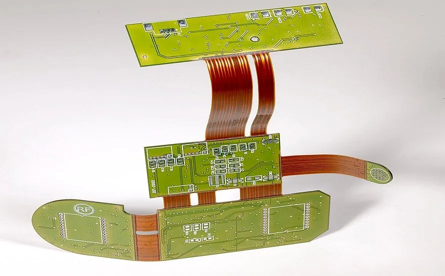
Flexible PCBs, or flexible printed circuit boards, are prized for their ability to bend and fit into tight spaces. However, their thickness isn’t just about how easily they can flex—it directly influences electrical performance, mechanical strength, and long-term reliability. A thinner flex PCB might be more flexible, but it could compromise signal quality or durability. On the other hand, a thicker flex PCB might enhance signal integrity but reduce bendability.
Choosing the right thickness is a balancing act. It requires understanding your application’s needs, such as high-speed signal transmission, frequent bending, or harsh environmental conditions. Let’s break down the key areas where flex PCB thickness makes a difference.
Flex PCB Thickness and Signal Integrity
Signal integrity refers to the quality of an electrical signal as it travels through a circuit. For high-speed applications like data transmission in telecommunications or computing, maintaining signal integrity is crucial. So, how does flex PCB thickness tie into this?
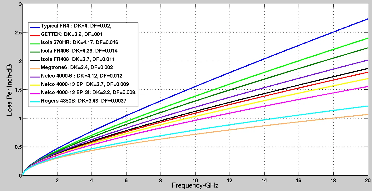
The thickness of a flex PCB affects the dielectric layer—the insulating material between conductive layers. A thinner dielectric can lead to higher capacitance between traces, which may cause signal crosstalk or interference. Conversely, a thicker dielectric reduces capacitance but might increase the board’s stiffness, limiting its flexibility. For example, in a high-speed design operating at 5 GHz, a dielectric thickness of 0.002 inches (2 mils) might introduce unwanted signal delay or loss compared to a slightly thicker 0.004 inches (4 mils) layer, depending on the material’s dielectric constant (Dk).
Material selection also plays a role alongside thickness. Polyimide, a common flex PCB material, has a dielectric constant of around 3.5, which impacts how signals propagate. Designers must balance thickness with material properties to minimize signal distortion, especially in applications requiring precise timing.
To optimize flex PCB thickness for signal integrity:
- Match the dielectric thickness to your signal speed requirements—thinner for low-speed, thicker for high-speed.
- Use simulation tools to predict signal behavior based on thickness and trace width.
- Consider controlled impedance designs to maintain consistent signal paths (more on this below).
PCB Thickness Impact on Impedance
Impedance, or the resistance to signal flow in a circuit, is another critical factor influenced by flex PCB thickness. Controlled impedance ensures that signals travel without reflections or loss, which is essential for high-speed digital and RF applications. But how does thickness affect impedance?
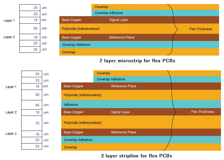
The impedance of a trace depends on its width, the distance to the ground plane (determined by dielectric thickness), and the dielectric constant of the material. A thinner dielectric brings the trace closer to the ground plane, lowering the impedance. For instance, a 50-ohm impedance line might require a trace width of 0.010 inches with a 0.002-inch dielectric. If the dielectric is reduced to 0.001 inches, the trace width must be adjusted narrower to maintain the same impedance, which can be challenging in manufacturing and may increase signal loss due to skin effect at high frequencies.
In flex PCBs, where space is often limited, achieving controlled impedance with ultra-thin layers can be tricky. A common solution is to use a thicker dielectric where possible or opt for materials with lower dielectric constants to maintain impedance without sacrificing flexibility. For example, switching to a material with a Dk of 2.5 instead of 3.5 can allow for a thinner design while keeping impedance in check.
Key tips for managing impedance through thickness:
- Work with your manufacturer to select the right dielectric thickness for your impedance targets (e.g., 50 ohms for RF signals).
- Account for bending areas—impedance can shift if the dielectric compresses during flexing.
- Use stack-up designs that balance thickness and flexibility for consistent impedance across the board.
Reliability of Thin Flex PCBs
Thin flex PCBs are often favored for their extreme flexibility and lightweight nature, making them ideal for wearables, medical implants, and aerospace applications. However, their reliability under stress—both mechanical and environmental—can be a concern. Let’s explore the trade-offs of using thin flex PCBs and how to ensure their durability.
Mechanical Reliability: Thinner flex PCBs, often below 0.004 inches (4 mils) in total thickness, are more prone to cracking or tearing during repeated bending. For example, a flex PCB with a bend radius of 0.5 inches might withstand 10,000 cycles if it’s 0.006 inches thick, but only 2,000 cycles if reduced to 0.002 inches. This is because thinner materials have less structural integrity to handle stress at tight bends.
Environmental Reliability: Thin flex PCBs are also more vulnerable to environmental factors like moisture and temperature changes. A thinner dielectric layer offers less protection against humidity, which can degrade the material over time. In automotive or outdoor applications, where temperatures can swing from -40°C to 85°C, a thicker flex PCB (e.g., 0.008 inches) might better resist thermal expansion and contraction.
Electrical Reliability: From an electrical standpoint, thin flex PCBs can struggle with current-carrying capacity. Thinner copper layers (common in ultra-thin designs) have higher resistance, leading to heat buildup and potential failure in high-current applications. For instance, a 0.5 oz copper layer on a thin flex PCB might handle only 1-2 amps before overheating, while a 1 oz layer on a thicker board could manage 3-4 amps safely.
To improve the reliability of thin flex PCBs:
- Add stiffeners in high-stress areas to prevent cracking without increasing overall thickness.
- Use protective coatings or coverlays to shield against moisture and debris.
- Opt for higher-grade materials with better tensile strength, even if they cost more.
Balancing Thickness with Application Needs
Every application has unique demands, and flex PCB thickness must align with those requirements. Here are some common scenarios and how thickness plays a role:
Wearable Technology: Devices like smartwatches need ultra-thin flex PCBs (often 0.002-0.004 inches) for maximum flexibility and comfort. However, designers must ensure signal integrity for wireless communication, often using controlled impedance traces despite the limited thickness.
Medical Devices: In applications like pacemakers, reliability is non-negotiable. A slightly thicker flex PCB (0.006-0.008 inches) might be used to improve durability and protect against body fluids, even if it sacrifices some flexibility.
Automotive Systems: Flex PCBs in vehicles face vibration and temperature extremes. A thicker design (0.008-0.012 inches) with robust materials can enhance mechanical reliability while maintaining signal quality for sensors and control systems.
By tailoring thickness to the specific use case, you can avoid over- or under-engineering your flex PCB, saving time and cost in the long run.
Design Tips for Optimizing Flex PCB Thickness
Creating a flex PCB with the right thickness for performance and reliability starts at the design stage. Here are actionable tips to guide you:
- Simulate Early: Use PCB design software to model how thickness affects signal integrity and impedance before prototyping. This can save costly revisions.
- Collaborate with Manufacturers: Work closely with your PCB provider to understand thickness limitations and material options. They can recommend stack-ups that balance flexibility and performance.
- Test for Reliability: Conduct bend tests and environmental stress tests on prototypes to ensure the chosen thickness holds up under real-world conditions.
- Prioritize Key Areas: Use varying thicknesses across the board if needed—thinner in bending zones, thicker in static areas with high-speed signals.
Common Challenges and Solutions
Designing with flex PCB thickness in mind isn’t without challenges. Here are a few common issues and how to address them:
Challenge 1: Signal Loss in Thin Designs
Solution: Use low-loss dielectric materials and adjust trace widths to compensate for thinner layers. Adding a ground plane can also help reduce interference.
Challenge 2: Cracking in Thin Flex PCBs
Solution: Reinforce critical bend areas with additional layers or stiffeners. Avoid sharp bends by increasing the bend radius where possible.
Challenge 3: Impedance Mismatch
Solution: Carefully calculate dielectric thickness and trace geometry during the design phase. Use impedance calculators or consult with your manufacturer for precision.
How ALLPCB Supports Your Flex PCB Needs
At ALLPCB, we understand the intricacies of flex PCB design, especially when it comes to optimizing thickness for performance and reliability. Our team offers expert guidance on material selection, stack-up design, and manufacturing processes to ensure your flex PCBs meet the highest standards. Whether you need ultra-thin boards for wearables or robust designs for industrial applications, we provide tailored solutions to bring your ideas to life.
Our advanced manufacturing capabilities allow for precise control over thickness, impedance, and signal integrity, backed by rigorous testing to guarantee reliability. Partner with us to streamline your design process and achieve superior results.
Conclusion: Making Informed Choices on Flex PCB Thickness
Flex PCB thickness is far more than a measure of bendability—it’s a deciding factor in signal integrity, impedance control, and long-term reliability. By understanding how thickness impacts these elements, you can design flexible circuits that perform flawlessly in your specific application. From managing signal loss with the right dielectric thickness to ensuring durability in thin flex PCBs, every decision shapes the success of your project.
Remember to balance flexibility with performance needs, leverage design tools for precision, and collaborate with experienced manufacturers like ALLPCB. With the right approach, you can harness the full potential of flex PCBs while avoiding common pitfalls. Start optimizing your designs today for better performance and reliability tomorrow.