 ALLPCB


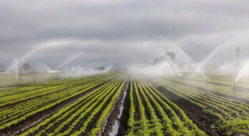
In the world of modern farming, automated irrigation systems are revolutionizing how we manage water resources and boost crop yields. If you're an engineer or hobbyist looking to create a smart agriculture system, designing a custom PCB (Printed Circuit Board) for automated irrigation is a game-changer. This blog will guide you through the essentials of designing PCBs for irrigation projects, focusing on key components, layouts, and practical tips for building an efficient automatic irrigation project. Whether you're working on agriculture PCB projects or exploring smart agriculture systems, this detailed guide has you covered.
What Are Automated Irrigation PCBs and Why Do They Matter?
Automated irrigation PCBs are the backbone of smart agriculture systems. These boards control sensors, valves, and communication modules to ensure crops get the right amount of water at the right time. By integrating technology into farming, these systems save water, reduce labor costs, and improve productivity. With global water scarcity on the rise, smart irrigation solutions powered by well-designed PCBs are more critical than ever.
In this post, we'll dive deep into designing PCBs for irrigation, covering everything from component selection to testing your board for real-world use. Let’s explore how you can create a reliable and efficient system for your next agriculture PCB project.
Understanding the Basics of Smart Agriculture Systems
Before jumping into PCB design, it’s important to understand what a smart agriculture system does. These systems use technology to monitor soil moisture, weather conditions, and crop needs, then automate irrigation based on real-time data. A typical setup includes:
- Sensors: Measure soil moisture, temperature, and humidity.
- Controllers: Process data and make decisions about when to water.
- Actuators: Control water valves or pumps to start or stop irrigation.
- Communication Modules: Send data to a user interface or cloud platform for remote monitoring.
The PCB ties all these components together, acting as the central hub for data processing and control. Designing a PCB for such a system requires careful planning to ensure reliability, especially in harsh outdoor environments.
Key Components for Automated Irrigation PCBs
When designing a PCB for an automatic irrigation project, selecting the right components is crucial. Here’s a breakdown of the essential parts you’ll need:
1. Microcontroller Unit (MCU)
The MCU is the brain of your smart agriculture system. It processes data from sensors and sends commands to actuators. Popular choices include microcontrollers with low power consumption, such as those with 8-bit or 32-bit architectures, supporting clock speeds around 16-80 MHz for efficient processing. Ensure the MCU has enough input/output pins for connecting sensors and actuators.
2. Soil Moisture Sensors
Soil moisture sensors measure the water content in the soil, typically outputting analog or digital signals. Look for sensors with a detection range of 0-100% moisture content and a working voltage of 3.3V to 5V to match your MCU specifications.
3. Temperature and Humidity Sensors
These sensors help monitor environmental conditions. A common choice operates within a temperature range of -40°C to 85°C and humidity range of 0-100% RH, with an accuracy of ±2°C and ±3% RH, ensuring precise data for irrigation decisions.
4. Relay Modules or MOSFETs
Relays or MOSFETs control high-power devices like water pumps or solenoid valves. A relay module rated for 5V control and 10A at 250V AC can handle most irrigation pumps, providing safe switching for your system.
5. Communication Modules
For remote monitoring, include a Wi-Fi or cellular module. Modules supporting 2.4 GHz Wi-Fi with data rates up to 150 Mbps are ideal for connecting your system to a smartphone app or cloud server.
6. Power Supply Components
Outdoor systems often need robust power management. Use voltage regulators to maintain a stable 5V or 3.3V output, and consider adding overvoltage protection circuits to handle input surges up to 12V or 24V from solar panels or batteries.
Steps to Design PCBs for Irrigation Systems
Designing a PCB for an automated irrigation system involves several steps. Follow this process to ensure your board meets the needs of a smart agriculture system.
Step 1: Define System Requirements
Start by listing the features your irrigation system needs. How many sensors will it support? Does it require wireless connectivity? Will it run on battery power or solar energy? Answering these questions helps determine the PCB’s size, power needs, and component count.
Step 2: Create a Schematic Diagram
Draw a schematic that connects all components logically. Place the MCU at the center, linking it to sensors via analog or digital pins, relays via digital output pins, and communication modules via serial interfaces like UART or SPI. Ensure proper grounding to minimize noise, especially for analog sensor readings.
Step 3: Design the PCB Layout
Once the schematic is ready, design the PCB layout. Keep these tips in mind:
- Component Placement: Group related components together. For example, place power supply components near the input connector to reduce voltage drop.
- Trace Width: Use wider traces (e.g., 20-30 mil) for power lines to handle currents up to 2A for relays or pumps.
- Ground Plane: Add a solid ground plane on one layer to reduce electromagnetic interference (EMI), which can affect sensor accuracy.
- Spacing: Maintain at least 10 mil spacing between traces to prevent short circuits, especially in humid outdoor conditions.
Step 4: Add Protection Features
Farming environments are tough on electronics. Include protection against moisture, dust, and voltage spikes. Use conformal coating on the PCB after assembly to protect against humidity. Add transient voltage suppressors (TVS diodes) rated for 24V to safeguard against power surges.
Step 5: Prototype and Test
After designing, create a prototype of your PCB. Test it under real conditions by connecting sensors and actuators. Check if soil moisture readings trigger the relay at the correct threshold (e.g., below 30% moisture). Measure signal integrity on critical lines using an oscilloscope to ensure no noise affects performance.
Challenges in Designing Agriculture PCB Projects
Designing PCBs for smart agriculture systems comes with unique challenges. Here are some common issues and how to address them:
- Environmental Durability: PCBs in fields face rain, dust, and temperature swings. Use weatherproof enclosures with IP65 or higher ratings to shield your board.
- Power Constraints: Remote locations may lack reliable power. Integrate solar panels with a charging circuit supporting 12V input and 5W output for sustainable operation.
- Signal Interference: Long sensor cables can pick up noise. Use shielded cables or add low-pass filters with a cutoff frequency of 100 Hz to clean up signals.
Software Integration for Automated Irrigation Systems
Beyond hardware, software plays a vital role in smart irrigation. Program your MCU to read sensor data every 10 minutes, compare it against thresholds (e.g., soil moisture below 25%), and activate relays for 5-10 minutes of watering. Use open-source platforms to develop mobile apps for remote control, ensuring data transmission over secure protocols like HTTPS.
For advanced systems, implement machine learning algorithms to predict irrigation needs based on weather forecasts. This requires a more powerful MCU or cloud integration, with data upload intervals of 30 minutes to balance power use and responsiveness.
Benefits of Using PCBs in Smart Agriculture Systems
Custom-designed PCBs bring several advantages to automated irrigation projects:
- Efficiency: Automating irrigation reduces water waste by up to 30-50% compared to manual methods.
- Scalability: A well-designed PCB can support multiple zones, controlling irrigation for different crop types in a single field.
- Cost Savings: Reduced labor and water usage lower operational costs by 20-40% over time.
These benefits make agriculture PCB projects a worthwhile investment for farmers and engineers alike.
Future Trends in Automated Irrigation and PCB Design
The field of smart agriculture is evolving rapidly. According to recent industry insights, the smart irrigation market is projected to reach $2.65 billion by 2030, growing at a compound annual growth rate (CAGR) of 10.8% from 2025. This growth is driven by innovations like AI integration for predictive irrigation and IoT for real-time data sharing.
For PCB designers, this means focusing on low-power designs, supporting LPWAN (Low Power Wide Area Network) protocols like LoRa for long-range communication with minimal power draw (e.g., 10-20 mA in active mode). Future PCBs may also need to handle edge computing, processing data locally to reduce latency in decision-making.

Tips for Successful Agriculture PCB Projects
To wrap up, here are some actionable tips to ensure your automatic irrigation project succeeds:
- Start small with a single-zone system before scaling to multi-zone setups.
- Use modular designs, allowing easy upgrades to sensors or communication modules.
- Test your PCB in simulated field conditions for at least 48 hours to identify weaknesses.
- Document your design process, including schematic and layout files, for future troubleshooting.
Conclusion: Building the Future of Farming with Automated Irrigation PCBs
Designing a PCB for a smart agriculture system is a rewarding endeavor that combines electronics with the critical need for sustainable farming. By carefully selecting components, optimizing your layout, and testing rigorously, you can create a reliable automated irrigation system that saves water and boosts crop health. Whether you’re a seasoned engineer or just starting with agriculture PCB projects, the steps and insights shared here will help you design PCBs for irrigation with confidence.
Embrace the power of technology to transform farming. With the right approach, your automatic irrigation project can contribute to a smarter, greener future in agriculture.


