 ALLPCB


If you're dealing with the complexities of BGA rework, especially with fine-pitch components, you're likely facing challenges like precise alignment, temperature control, and defect prevention. In this comprehensive guide, we dive deep into the BGA rework process, explore solutions for fine pitch rework, and provide actionable insights on using BGA rework equipment, optimizing BGA rework temperature profiles, and minimizing BGA rework defects. Whether you're an experienced engineer or new to PCB assembly, this post will equip you with the knowledge to tackle these challenges head-on.
What Makes BGA Rework So Challenging?
Ball Grid Array (BGA) components are widely used in modern electronics due to their compact size and high pin density. Unlike traditional through-hole components, BGAs connect to the PCB through an array of solder balls underneath the package. While this design saves space and supports complex circuits, it creates significant hurdles during rework and repair. The main challenges include hidden connections, tight spacing in fine-pitch components, and the need for precise heat application to avoid damaging the board or nearby parts.
Fine-pitch BGAs, with ball spacing as small as 0.4mm or less, amplify these issues. A slight misalignment or uneven heating can lead to defects like solder bridging or insufficient bonding. Let's break down these challenges and explore practical ways to master the BGA rework process.
Key Challenges in the BGA Rework Process
The BGA rework process involves removing a faulty BGA component, cleaning the site, and soldering a new one in place. Each step comes with potential pitfalls that can compromise the quality of the repair. Here are the primary challenges engineers face:
1. Precise Component Removal
Removing a BGA without damaging the PCB or adjacent components is tricky. The solder balls are hidden beneath the package, so you can't visually confirm when the solder has melted. Applying too much heat can warp the board, while insufficient heat may lift pads or traces. Typically, a hot air rework station is used, with temperatures ranging from 300°C to 350°C for lead-free solder, depending on the alloy composition.
2. Cleaning and Site Preparation
After removal, residual solder must be cleared from the PCB pads. Fine-pitch components, with their tight spacing, make this step even harder. Leftover solder or debris can prevent proper bonding during reattachment, leading to defects. Specialized wicking braids and low-temperature soldering irons (around 250°C) are often used to avoid overheating delicate pads.
3. Alignment and Placement
Realigning a BGA component, especially a fine-pitch one, requires extreme precision. Misalignment by even 0.1mm can result in open circuits or shorted connections. Advanced BGA rework equipment with optical alignment systems can help achieve accuracy down to 0.01mm, ensuring the solder balls match the PCB pads perfectly.
4. Managing Thermal Stress
Uneven heating during rework can cause thermal stress, leading to board warpage or component cracking. Fine-pitch BGAs are particularly sensitive due to their smaller size and denser connections. A well-designed BGA rework temperature profile is critical to heat the component and board uniformly, typically involving a preheat phase at 150°C to 180°C before reflow.
Mastering Fine Pitch Rework: Tips and Techniques
Fine pitch rework demands extra care due to the reduced spacing between solder balls. With pitches as tight as 0.3mm or 0.4mm, even minor errors can cause catastrophic failures. Here are proven strategies to handle fine-pitch BGAs effectively:
1. Use High-Precision Equipment
Invest in BGA rework equipment designed for fine-pitch components. Look for systems with split-vision optics that allow you to see both the component and PCB pads simultaneously for accurate alignment. Placement accuracy of 0.025mm or better is ideal for fine-pitch applications.
2. Optimize Stencil Design
When applying solder paste for fine-pitch BGAs, use a stencil with apertures slightly smaller than the pad size (about 80-90% of the pad diameter) to prevent excess paste and reduce the risk of bridging. For a 0.4mm pitch, stencil thickness should be around 0.1mm to control paste volume precisely.
3. Control Solder Paste Application
Apply solder paste evenly using a micro-stencil or automated dispensing system. Excess paste can cause shorts between closely spaced balls, while insufficient paste leads to weak joints. Aim for a paste height of about 0.05mm to 0.08mm for fine-pitch components.
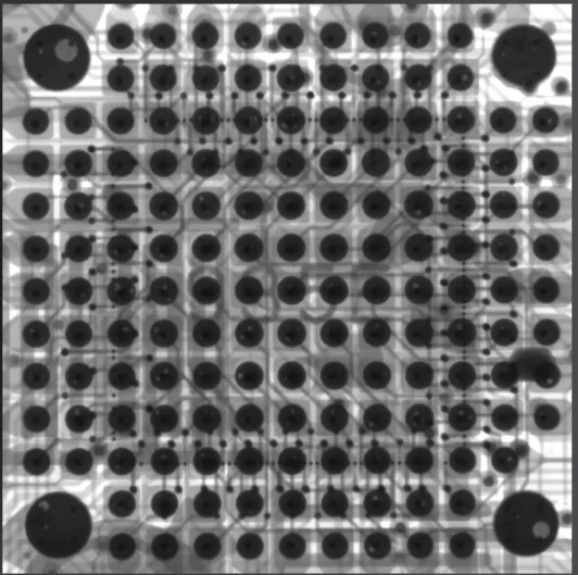
4. Inspect Before Reflow
Before reflowing, use X-ray inspection to verify alignment and paste distribution. X-ray systems can detect misalignments or voids in the paste layer that aren't visible to the naked eye, reducing the chance of BGA rework defects.
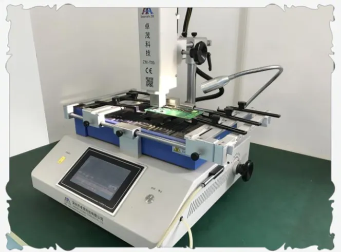
The Role of BGA Rework Equipment in Success
Having the right BGA rework equipment can make or break your rework process. Modern rework stations are equipped with features to handle the intricacies of fine-pitch components. Here's what to look for:
- Hot Air Systems: Choose a station with adjustable airflow and temperature settings. Airflow rates of 20-30 liters per minute and temperature control within ±5°C ensure precise heating without overheating.
- Optical Alignment: For fine-pitch rework, equipment with high-resolution cameras and split-vision systems is essential for aligning components with pads spaced less than 0.5mm apart.
- Preheaters: Bottom-side preheaters help maintain a uniform board temperature (around 150°C) during rework, reducing thermal stress and preventing warpage.
- Nozzle Variety: Use nozzles sized to match the BGA package dimensions. For a 10mm x 10mm component, a nozzle slightly larger (12mm x 12mm) ensures even heat distribution.
Investing in advanced equipment not only improves rework quality but also boosts efficiency, reducing the time spent on each repair cycle.
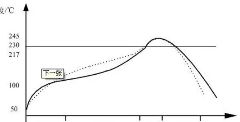
Crafting the Perfect BGA Rework Temperature Profile
A well-defined BGA rework temperature profile is the backbone of a successful rework process. Incorrect temperatures or ramp rates can lead to defects like cold solder joints, component damage, or board delamination. Here's how to optimize your profile:
1. Preheat Phase
Start by preheating the PCB to 150°C-180°C for 60-90 seconds. This minimizes thermal shock and ensures the board reaches a stable temperature before reflow. For fine-pitch components, keep the preheat on the lower end to avoid excessive heat buildup.
2. Soak Phase
Gradually raise the temperature to 200°C-220°C over 30-60 seconds. This soak phase activates the flux in the solder paste, removing oxides and preparing the surfaces for bonding.
3. Reflow Phase
Increase the temperature to the solder's liquidus point, typically 300°C-350°C for lead-free solder, and hold for 30-45 seconds. For fine-pitch BGAs, monitor the peak temperature closely to avoid overheating small solder balls, which can melt unevenly.
4. Cooling Phase
Allow the board to cool naturally or use controlled cooling at a rate of 2-4°C per second. Rapid cooling can cause thermal stress, leading to cracks in fine-pitch solder joints.
Adjust these parameters based on the specific solder alloy and component size. Always refer to the manufacturer's datasheet for recommended profiles, as variations in materials can affect the ideal settings.
Common BGA Rework Defects and How to Avoid Them
Even with the best equipment and profiles, BGA rework defects can occur if attention to detail is lacking. Here are the most common issues and tips to prevent them:
1. Solder Bridging
This happens when excess solder connects adjacent balls, especially in fine-pitch BGAs with spacing below 0.5mm. Prevent it by using the correct stencil aperture size and inspecting paste application before reflow.
2. Cold Solder Joints
Insufficient heat or poor flux activation can result in weak, incomplete bonds. Ensure your BGA rework temperature profile reaches the proper reflow temperature (above 300°C for lead-free solder) and verify flux quality.
3. Voids in Solder Joints
Voids occur when gas gets trapped during reflow, weakening the joint. Use X-ray inspection post-rework to detect voids (aim for less than 25% voiding per joint as per industry standards like IPC-7095) and adjust the soak phase to allow gas escape.
4. Component Misalignment
Misaligned components fail to connect properly, leading to open circuits. Use optical alignment tools during placement and confirm positioning with X-ray imaging before reflow.
5. Board Warpage
Excessive heat or uneven temperature distribution can warp the PCB, misaligning pads. Use a preheater and keep peak temperatures within 10°C of the recommended maximum (usually 350°C for most boards).
Best Practices for Consistent BGA Rework Success
To achieve reliable results in the BGA rework process, follow these best practices:
- Always document your temperature profiles and equipment settings for each type of BGA and PCB. Consistency reduces trial-and-error.
- Train technicians on fine-pitch handling and equipment use. Human error accounts for a significant portion of rework defects.
- Invest in regular maintenance of BGA rework equipment. Clean nozzles, calibrate temperature sensors, and check alignment systems to ensure accuracy.
- Use high-quality solder paste and flux compatible with your components. For lead-free applications, pastes with SAC305 alloy (Sn96.5/Ag3.0/Cu0.5) offer good reliability.
- Perform post-rework testing, including electrical continuity checks and X-ray inspections, to confirm joint quality.
Conclusion: Overcoming BGA Rework Challenges
Mastering the BGA rework process, especially for fine-pitch components, requires a combination of precision, the right BGA rework equipment, and a carefully controlled BGA rework temperature profile. By understanding the unique challenges of fine pitch rework and implementing strategies to avoid BGA rework defects, you can achieve consistent, high-quality results. From optimizing alignment to preventing thermal stress, every step matters in ensuring the reliability of your PCB assemblies.
With the tips and techniques outlined in this guide, you're well-equipped to tackle even the most complex BGA rework tasks. Focus on precision, invest in quality tools, and always prioritize thorough inspection to keep your projects on track.


