ALLPCB


Introduction
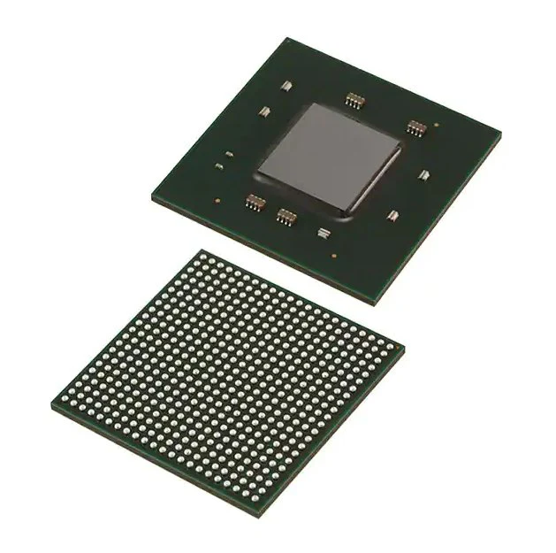
Xilinx Versal, UltraScale, 7-series and 6-series devices are available in multiple BGA package pitches to support different performance and routing requirements. These packages commonly use four pitch sizes: 1.0 mm, 0.92 mm, 0.8 mm and 0.5 mm. This article summarizes PCB layer count estimation, BGA pad design (NSMD vs SMD), via planning, and routing considerations for these pitch families.
1. BGA pad pitch
The primary factor that determines BGA routing complexity is the ball pitch. Other important factors include the BGA array size, solder mask type, and required PCB stackup. Pitch is defined as the center-to-center spacing between adjacent BGA pads.
Xilinx recommends non-soldermask-defined (NSMD) copper BGA pads for optimal board design. NSMD pads are exposed copper not covered by solder mask, while soldermask-defined (SMD) pads have a portion of the pad covered by solder mask. The two styles differ in pad-to-mask clearance and manufacturing characteristics.
2. Layer estimation and optimization
2.1 Layer count estimation
A quick method to estimate the number of PCB signal layers required to fully fan out a BGA uses a simple relationship based on the number of signals, routing channels, and routes per channel.
Signals: For Xilinx FPGAs, MPSoC/ RF SoC and AC AP devices, signal count is commonly estimated at roughly 60% of the BGA balls; the remaining ~40% are power and ground and are typically routed to dedicated internal planes via vias. This estimate assumes 100% I/O utilization; fewer active I/Os reduce the required signal routing.
Routing channels: Defined as the available routing tracks leaving the BGA region (number of balls per side minus one, multiplied by four sides).
Routes per channel: Typically one or two routes per channel depending on whether one or two signals are routed between adjacent pads. Using these parameters yields an approximate number of signal layers required for full routing of a given package.
2.2 Layer count optimization
Although Xilinx packages use a full ball grid array, the actual number of layers required depends on multiple factors: BGA size (pin count), pad size, pad pitch and trace width, fixed-pin constraints, backdrilling, and manufacturing capabilities.
1) BGA size (pin count)
The number of BGA pins correlates with the number of signals to route. Physical area constraints mean that more signals generally require more signal layers.
2) Pad size, pad pitch and trace width
Pad size and pitch determine the available space for fanout between adjacent pads. Depending on chosen trace width, one or two traces can be routed between pads. If one trace is fanned out between adjacent pads, that trace can be routed on a single signal layer; the outermost BGA row typically allows two traces per layer (and in some cases three on the very outermost row). It is acceptable to narrow trace width within the BGA fanout area to allow additional routes, then widen traces once clear of the fanout; short width changes can cause only minor impedance variations.
3) Fixed pins
Certain signals have fixed ball locations (for example, JTAG, transceiver I/O and memory controller signals). These fixed positions reduce routing flexibility relative to signals that can be swapped, and may increase the number of signal layers required.
4) Backdrilling
Backdrilling removes unused via stubs to reduce reflections that can harm signal integrity. Note that manufacturability constraints on backdrilling can affect the ability to route multiple signals between a pad and a via. Always consult the PCB fabricator regarding backdrilling capabilities before finalizing layout and stackup.
5) Manufacturing technologies
Several advanced PCB fabrication techniques can reduce the number of signal layers required, at increased manufacturing cost:
- Blind vias (+20% to +40% cost): Blind vias connect an outer layer to one or more inner layers without going through the entire board, freeing routing space above or below.
- Buried vias (+25% to +60% cost): Buried vias are entirely internal to the printed circuit board and do not reach the outer layers.
- Via-in-pad (+10% to +20% cost): Placing vias directly in BGA pads allows signals to be routed down immediately from the pad to an inner layer, easing escape routing under dense BGAs and improving impedance control on outer layers by removing conflicting traces from the top/bottom.
2.3 Maximum board thickness and aspect ratio
The aspect ratio is the ratio of board thickness to minimum hole diameter; higher ratios increase manufacturing difficulty. Maximum board thickness is a function of the minimum drill diameter and the allowable aspect ratio, both provided by the PCB manufacturer. Typical 15:1 ratios indicate board thickness should not exceed 15 times the drill diameter. For example, a 10 mil drill implies a 150 mil maximum board thickness at 15:1. For many Xilinx packages, finished drill diameters of 10–15 mil are recommended, with a plated-hole diameter reduced by plating by roughly 3 mil. Advanced fabrication can support aspect ratios from roughly 17:1 to 22:1 at additional cost.
3. Recommended BGA pad, via and trace dimensions for 1.0 mm, 0.92 mm, 0.8 mm and 0.5 mm devices
3.1 Recommended pad and via dimensions
Xilinx defines pad and via dimensions for FPGA/ACAP ball pads and vias per device pitch. A reference table provides recommended physical dimensions based on BGA ball pitch.
3.2 Recommended routing between pads and vias
BGA pitch and pad/via diameters determine the remaining space available for routing between pads or between vias. Standard PCB fabrication can typically support trace widths down to about 3.5 mil; advanced processes can allow trace widths down to about 2 mil. Recommended trace routing varies by pitch and pad/via size to allow one or two traces between pads where feasible.
3.3 Recommended routing between vias
One or two traces can be routed between vias for 1.0 mm, 0.92 mm and 0.8 mm pitch devices. Routing between vias at 0.5 mm pitch is generally impractical without using via-in-pad technology to increase available spacing. Via-in-pad is recommended for the densest pitches to facilitate escape routing.
Note: Specific numeric pad, via and trace dimension tables are provided by the device manufacturer and PCB fabricator; use those references when defining final pad geometries and stackup.