ALLPCB


Introduction
Wire harnesses on vehicles can be classified by waterproofing as dry-zone or wet-zone harnesses, and by whether their attachment points move as static or dynamic harnesses. EPB caliper harnesses and wheel speed sensor harnesses are fixed to the axle assembly, operate in the wet zone, and experience large displacements during vehicle operation. To improve the consistency and efficiency of design reviews and quality control for these harnesses, this article systematically describes their characteristics, common structures, routing and layout, material selection, design basis, key dimensions, evaluation items and performance requirements, and provides guidance for designing harnesses in moving vehicle areas.
Function Overview and Common Structures
2.1 Function Overview
The EPB caliper harness transmits power to the caliper motor and carries wheel speed signals. For example, when the parking brake is required, the EPB switch signal is sent to the electronic control unit, which operates the motor and reduction gear to actuate the brake caliper via the EPB caliper harness.
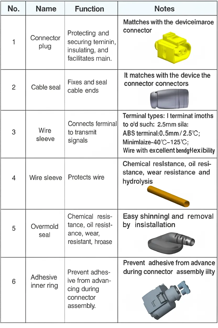
2.2 Common Structures
Materials for EPB caliper harnesses are listed below.
3 Harness Routing and Layout Forms
3.1 Design Basis for Harness Routing
EPB caliper harnesses and wheel speed sensor harnesses are normally routed on the axle assembly. Due to axle motion and harsh surrounding conditions, routing in this area is critical for safety and durability. Based on prior design experience and vehicle validation, the following routing considerations apply.
3.1.1 Requirements for Dynamic Routing Sections
- Do not use bundled-tie type clamps as fixed points within dynamic sections.
- Both ends of the dynamic section must be secured with injection-molded grommets; the fixed points must not separate from the sheet metal during 40 Hz bending motion.
- Where possible, place fixed points on the rear axle closer to the front to reduce motion amplitude.
- Injection-molded grommets at both ends of the dynamic section must have a woven tail structure to disperse stress.
- Control the motion envelope of moving sections using guide-type fixed grommets where appropriate.
- Design movement of dynamic and static points preferably with parallel sliding layouts; secondarily use C-shaped sliding layouts.
- Keep the motion trajectory of moving sections as planar as possible to avoid spiral trajectories.
- The harness length between two dynamic points must not exceed 300 mm and must accommodate maximum upward/downward wheel travel and left/right steering extremes; motion simulation must verify no relative shear motion or interference.
- Reserve slack length based on actual vibration amplitude and maximum travel of moving parts to prevent vibration transfer to the harness and to avoid tension on the harness. Recommended minimum bend radius is 5D (D = harness outer diameter).
- Clearance to moving parts should be ≥ 25 mm; distance from exhaust manifold should be > 50 mm.
- Do not cross or contact fuel lines or brake lines, especially at harness or fluid connections.
- Wheel speed sensor harness routing must ensure sufficient clearance between the harness and the wheel throughout the wheel's rotation.
3.1.2 Requirements for Relative Static Areas
- Design branch clip length at the wheel-speed end to be no greater than 100 mm; do not exceed 150 mm.
- Wheel speed sensors should allow assembly and disassembly with powered screwdrivers.
- Consider connector and accessory sealing in layout; use injection-molded structures to ensure sealing; if injection molding is not feasible, use sealing rings with rated waterproof performance.
- Caliper-end assembly space should accommodate at least twice the connector length.
- Place connectors where they are visible and accessible by hand and tools for inspection and maintenance; plan harness service length based on actual assembly conditions.
- When placing fixed points, account for sag due to harness weight; maintain gap between harness and nearby parts ≥ 15 mm.
- Avoid harness interference with surrounding components; ensure clearance and consider rigid conduits or brackets to prevent harness deformation.
- Maintain sufficient distance between caliper harness assemblies and heat sources (≥ 20 mm), or use closed corrugated tubing rated to 150°C, or protect with aluminum foil shielding.
- Clip spacing should be ≤ 200 mm; use one fixed point at obtuse corners and two at right-angle corners.
- Inline connector placement should be located away from the wheel spray area, in the dry zone.
3.2 Comparative Analysis of Layout Forms
3.2.1 Tire and Axle Envelope
Wheels move in multiple directions. During harness data-driven design, first determine the working environment and motion trajectories of surrounding parts such as the axle and wheel envelopes.
3.2.2 Layout Examples
Routing cannot be identical across vehicles, but minimizing motion in the dynamic section is key to improving caliper harness reliability. Two common layout approaches:
- Route along the axle to reduce harness motion amplitude.
- Arrange the harness between moving and static points in a straight-line layout.
4 Conductor Design Basis and Recommendations
Because caliper and wheel-speed harnesses are located on moving parts and are subject to continuous motion, conductor flexibility is important. Recommended requirements include:
- Passenger-vehicle low-voltage wire operating temperature range: -40 to 125 °C.
- For 0.5 mm^2 cross-section wire: lay length 25 ± 3 mm, S-stranding direction.
- Selected wire should withstand one million flex cycles (room temperature: 600,000 cycles at 2.5 Hz; -20 °C: 250,000 cycles at 1 Hz; -40 °C: 150,000 cycles at 1 Hz).
- Meet C-level requirements of GB/T 25085-2010 (Chinese standard).
5 PUR Tubing: Design Basis and Recommendations
PUR tubing protects the wires and is critical to the reliability of caliper and wheel-speed harnesses. Recommended material and structural guidelines:
- Select tubing material that bonds well with the material of the injection-molded grommet; ideally use the same material for both.
- PUR tubing should be abrasion-resistant, flexible, resistant to stone-chip impact, resistant to chemical reagents, resistant to atmospheric corrosion, hydrolysis-resistant, anti-aging, and resistant to fuel, lubricants or grease.
- Select tubing size per the referenced table, with a target wire fill ratio of approximately 80%.
- PUR tubing should extend into the grommet by at least 10 mm.
- Operating temperature range: -40 to 125 °C.
- Materials should be selected to meet OEM ELV (End-of-Life Vehicle) requirements where applicable.
6 Fixed Grommet Material: Design Basis and Recommendations
Fixed grommets bear the tensile loads generated during motion of caliper and wheel-speed harnesses, so tensile strength is a key design consideration. Tests indicate injection-molded grommets can withstand tensile loads greater than 200 N. Using the same material for the fixed grommet and PUR tubing improves overmolding performance.
- Recommended material for injection-molded sheet-metal grommets: polyurethane (PUR) with 75A hardness.
- Grommet material should be abrasion-resistant, flexible, resistant to stone-chip impact, resistant to chemical reagents, resistant to atmospheric corrosion, hydrolysis-resistant, anti-aging, and resistant to fuel, lubricants or grease.
- Operating temperature range: -40 to 125 °C.
7 Sheet-Metal Bracket: Design Basis and Forms
Fixed grommets are mounted on sheet-metal brackets; matching dimensions between the two is essential to secure the harness and ensure reliability. Vehicle validation indicates the following key fit dimensions:
- For grommet diameter versus sheet-metal hole: single-side interference tolerance 0.2 mm > interference ≥ -0.20 mm. Grommet groove width versus sheet-metal thickness: 0.2 mm > interference ≥ -0.2 mm. Grommet diameter should exceed the bracket stop dimension by 3-4 mm.
- Define insertion/extraction forces for grommet and sheet metal between 30 and 90 N; consider the grommet assembly contact surface and ensure grommet retention slot depth ≥ 1.5 mm.
- Chamfer sheet-metal stop to R3 to prevent cutting the grommet during insertion.