 ALLPCB


Introduction
USB has become the standard method for devices to communicate with PCs. From removable flash drives and mice to dedicated devices for specific applications, this widely adopted standard has largely replaced other serial communication protocols.
Under the USB specification, USB devices cannot communicate directly with each other. They can only communicate with a USB host that controls the bus and one or more devices. A common USB host is a PC. This application note discusses USB embedded hosts that enable embedded applications to use various USB devices. It also introduces Microship microcontrollers with a USB On-The-Go (OTG) module.
USB Overview
There are many references on USB, including the USB 2.0 specification itself, which provides detailed information on USB operation. This section only provides brief definitions of terms referenced in this document or required to understand stack operation.
USB Hosts and Peripherals
A typical USB system consists of a host and one or more peripheral devices (commonly called "devices"). Each device can only communicate with the host; devices generally cannot communicate directly with each other. The host initiates all traffic on the bus. Devices may send data to the host only in response to host requests, and they must be able to receive data sent by the host. Devices typically use a Type B receptacle or have a fixed cable.
Most USB peripherals are organized into classes. Each class has specific requirements for its communication format. The host must recognize a device's class and satisfy that class's requirements; otherwise, the host cannot communicate with the device. Examples of classes include HID (human interface device), such as mice, and mass storage, such as flash drives. Client drivers provide application-level support for classes. Some USB peripherals are vendor-specific and do not belong to predefined classes; client drivers for those devices must be written specifically for them.
The number of devices that can be connected to a host can be expanded using hubs. USB is a tiered star topology. Typically, a hub allows four or seven devices to be connected to a single port. Up to five hubs can be linked together, creating up to five tiers. A maximum of 127 devices (including hubs) can be connected to the bus.
A full-featured USB host uses a Type A receptacle and must be able to communicate with any device. This support can be provided via special drivers that must be installed on the host before connecting certain devices. Hubs must be supported, and each port must be able to supply at least 100 mA of current.
Host vs Embedded Host
USB embedded hosts differ from full USB hosts in several small but important ways. USB embedded hosts:
- Support only specific peripherals and/or device classes.
- Support only the transfer types required by the supported devices.
- May make hub support optional.
- Have relaxed power requirements.
These restrictions allow embedded hosts to be implemented on devices with fixed, limited memory.
Host-Mode Operation
In a USB system, the host controls all traffic on the bus. Devices only respond to requests from the host; they may not initiate data transfers. USB OTG modules can operate in either host or device mode. The exact operation differs between the two modes.
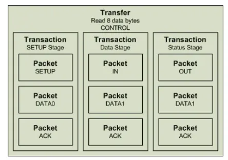
USB transfers can contain multiple transactions, and transactions can contain multiple packets. Additionally, a single transfer can include multiple data-phase transactions. Figure 1 shows the general format of a single USB transfer.

Control transfers typically require all three transactions. The structure of a control transfer that reads eight data bytes is shown in Figure 2.
Bulk, interrupt, and isochronous transfers do not use SETUP tokens or status transactions. For bulk transfers, up to 64 bytes can be transferred in a single data-phase transaction. A bulk write of 128 data bytes requires two data-phase transactions, as shown in Figure 3.
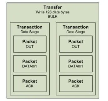
The USB embedded host stack connects to the USB OTG module in host mode at the packet level, while ACK packets are handled automatically by the module. When the embedded host issues the bulk transfer shown in Figure 3, it must explicitly issue commands to transmit the two OUT and two DATA0/1 packets. When the embedded host issues the control transfer shown in Figure 2, it must explicitly issue commands to transmit all SETUP, DATA0/1, IN, and OUT packets, a total of six packets.


