ALLPCB


Thermal profiling is a critical step in PCB assembly, ensuring that components are soldered correctly during the reflow process. However, issues like reflow oven temperature variations, thermocouple placement problems, and challenges in analyzing thermal profiling data can lead to common reflow defects. In this guide, we’ll dive deep into troubleshooting PCB assembly thermal profiling problems with practical solutions to help you achieve reliable and high-quality results. Whether you're dealing with inconsistent heating or defective solder joints, this blog offers actionable insights to optimize your process.
What is Thermal Profiling in PCB Assembly?
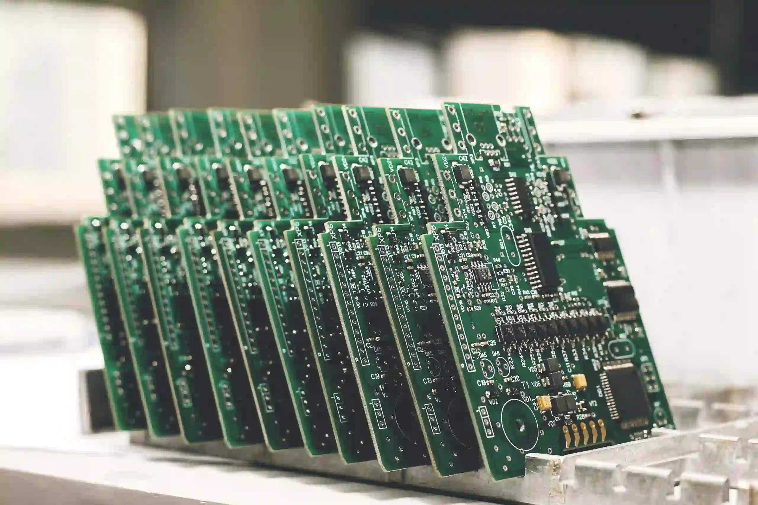
Thermal profiling refers to the process of measuring and recording the temperature changes a printed circuit board (PCB) experiences during the reflow soldering process. This is typically done using thermocouples, which are small sensors attached to specific points on the PCB to capture real-time temperature data. The goal is to create a temperature profile that matches the solder paste and component requirements, ensuring proper soldering without damaging sensitive parts.
A well-executed thermal profile ensures that the PCB passes through key stages—preheat, soak, reflow, and cooling—at the right temperatures and durations. However, PCB assembly thermal profiling problems can disrupt this balance, leading to defects and reduced reliability. Let’s explore the most common issues and how to address them.
Common PCB Assembly Thermal Profiling Problems
Thermal profiling issues can arise from various sources, including equipment limitations, operator errors, and environmental factors. Below, we break down the most frequent challenges faced during PCB assembly.
1. Reflow Oven Temperature Variations
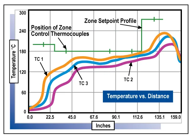
One of the most significant hurdles in thermal profiling is managing reflow oven temperature variations. These inconsistencies can occur due to uneven heat distribution across the oven zones or malfunctioning heating elements. For instance, if the temperature in one zone spikes beyond the recommended 220°C for lead-free solder paste, it may cause component damage or incomplete soldering in cooler areas.
Impact: Temperature variations often lead to defects like tombstoning, where one end of a component lifts off the pad, or insufficient solder wetting, resulting in weak joints.
Solution: Regularly calibrate your reflow oven to ensure uniform heat distribution. Use a profiling tool to measure the temperature across different zones—typically, modern ovens have 5 to 10 zones—and adjust settings to maintain a consistent gradient. Additionally, ensure proper maintenance of fans and heaters to prevent hot or cold spots. A deviation of more than ±5°C across zones often signals the need for immediate recalibration.
2. Thermocouple Placement Issues
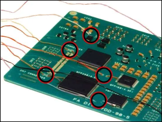
Thermocouples are essential for accurate thermal profiling, but incorrect placement can skew data and mislead your process adjustments. For example, placing a thermocouple too close to a large heat sink or thermal mass can result in lower-than-actual readings, while placing it near a high-heat component might show exaggerated temperatures.
Impact: Poor placement can lead to an inaccurate thermal profile, causing over- or under-heating during reflow. This might result in defects like solder voids or burnt components.
Solution: Identify the hottest and coldest spots on your PCB by testing multiple locations during initial profiling runs. Place thermocouples on critical components, such as those with high thermal mass (e.g., large capacitors) or small, sensitive parts (e.g., fine-pitch ICs). Secure them with high-temperature tape or adhesive to prevent movement during the process. Aim to monitor at least 3-5 points on the board for a comprehensive profile.
3. Challenges in Analyzing Thermal Profiling Data
Once the thermal data is collected, analyzing thermal profiling data can be daunting, especially for complex boards with varying component densities. Misinterpreting key metrics like Time Above Liquidus (TAL) or peak temperature can lead to incorrect oven settings. For instance, a TAL below 30 seconds for lead-free solder might not allow enough time for proper joint formation, while exceeding 90 seconds could overstress components.
Impact: Incorrect analysis often results in recurring defects and wasted production time as you troubleshoot without addressing the root cause.
Solution: Use thermal profiling software to visualize and interpret data effectively. Focus on critical parameters like the slope of the preheat phase (ideally 1-3°C per second), TAL (30-90 seconds for most solders), and peak temperature (typically 235-250°C for lead-free solder). Compare your profile against the solder paste manufacturer’s specifications, and adjust oven settings iteratively to match the ideal curve. Document each run to track trends and identify recurring issues.
4. Environmental and External Factors
External factors like ambient temperature, humidity, or airflow in the production area can also affect thermal profiling. For example, a sudden draft near the reflow oven might cool certain zones, causing temperature inconsistencies.
Impact: These factors can introduce variability, making it harder to achieve repeatable results and increasing the risk of defects.
Solution: Maintain a controlled environment around the reflow oven, ideally with a temperature of 20-25°C and minimal airflow disruptions. Use insulated enclosures if necessary to shield the oven from external influences. Regularly monitor ambient conditions to correlate them with profiling data anomalies.
Common Reflow Defects Linked to Thermal Profiling Issues
Thermal profiling problems often manifest as specific reflow defects that compromise the quality of the PCB. Understanding these defects can help you trace back to the root cause in your thermal profile. Here are some of the most common issues:
1. Tombstoning
Tombstoning occurs when a small component, like a resistor or capacitor, stands upright on one end due to uneven heating or solder melting. This often happens when one pad reaches reflow temperature before the other, causing imbalanced surface tension.
Cause: Reflow oven temperature variations or an overly steep preheat slope (above 3°C per second).
Solution: Adjust the preheat zone to a gradual slope of 1-2°C per second to ensure uniform heating. Verify that both pads of small components are within the same thermal zone during profiling.
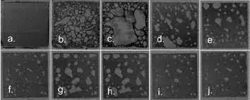
2. Solder Voids
Solder voids are air pockets within a solder joint, reducing its mechanical strength and electrical conductivity. They are often caused by insufficient time above liquidus or trapped flux volatiles due to rapid cooling.
Cause: Incorrect TAL (below 30 seconds) or improper cooling rates.
Solution: Extend the TAL to 40-60 seconds by adjusting the reflow zone temperature or conveyor speed. Ensure a controlled cooling rate of 2-4°C per second to allow gases to escape.
3. Insufficient Wetting
Insufficient wetting happens when solder fails to fully bond with the pad or component lead, often due to low peak temperatures or short reflow times.
Cause: Peak temperature below the recommended range (e.g., under 235°C for lead-free solder).
Solution: Increase the peak temperature to match the solder paste specification, typically 240-250°C for lead-free alloys. Ensure the reflow zone duration is adequate for complete melting.
4. Component Damage or Warpage
Excessive heat or prolonged exposure to high temperatures can damage sensitive components or cause PCB warpage, leading to misalignment or cracks.
Cause: Peak temperature exceeding component limits (e.g., above 260°C) or extended TAL.
Solution: Review component datasheets for maximum temperature ratings and adjust the profile to stay within safe limits. Reduce conveyor speed if necessary to shorten high-temperature exposure.
Best Practices for Effective Thermal Profiling in PCB Assembly
To minimize PCB assembly thermal profiling problems and prevent common reflow defects, follow these best practices:
- Regular Equipment Calibration: Calibrate your reflow oven monthly or after any maintenance to ensure consistent performance. Check for temperature deviations across zones and address them promptly.
- Strategic Thermocouple Placement: Place thermocouples on areas with varying thermal mass to capture a complete picture of the board’s behavior. Avoid placing them near edges or vents where readings may be skewed.
- Use Advanced Profiling Tools: Invest in modern profiling systems that offer real-time data and predictive analytics to fine-tune your process without manual guesswork.
- Iterative Testing: Run multiple profiling tests on dummy boards before full production to identify and correct issues like reflow oven temperature variations or thermocouple placement issues.
- Document and Review: Keep detailed records of each thermal profile, including oven settings, ambient conditions, and defect rates. Use this data to refine your process over time.
Advanced Techniques for Analyzing Thermal Profiling Data
For engineers looking to take their thermal profiling to the next level, advanced techniques can provide deeper insights and improve process control.
1. Virtual Profiling
Virtual profiling uses software to simulate thermal behavior without attaching thermocouples for every run. After an initial setup with physical measurements, the system can predict profiles based on oven settings and board characteristics.
Benefit: Saves time and reduces the risk of thermocouple placement issues by automating data collection and analysis.
2. Statistical Process Control (SPC)
SPC involves using statistical methods to monitor and control the reflow process. Metrics like Process Window Index (PWI) help quantify how well your profile fits within acceptable limits.
Benefit: Identifies trends and variability in thermal profiling data, allowing proactive adjustments before defects occur.
3. Design of Experiments (DOE)
DOE is a structured approach to test different oven settings and board configurations to find the optimal thermal profile. For example, varying conveyor speed and zone temperatures systematically can reveal the best combination for a specific PCB design.
Benefit: Provides data-driven solutions to complex thermal profiling challenges, minimizing trial-and-error.
Conclusion: Mastering Thermal Profiling for Reliable PCB Assembly
Troubleshooting PCB assembly thermal profiling problems is essential for achieving high-quality, reliable solder joints and minimizing common reflow defects. By addressing issues like reflow oven temperature variations, thermocouple placement issues, and challenges in analyzing thermal profiling data, you can optimize your process for consistent results. Implementing the practical solutions and best practices outlined in this guide will help you overcome these hurdles and enhance your production efficiency.
Thermal profiling may seem complex, but with the right tools, strategies, and attention to detail, it becomes a manageable and critical part of successful PCB assembly. Keep refining your approach, stay updated with industry advancements, and ensure your equipment is in top shape to maintain a competitive edge in electronics manufacturing.