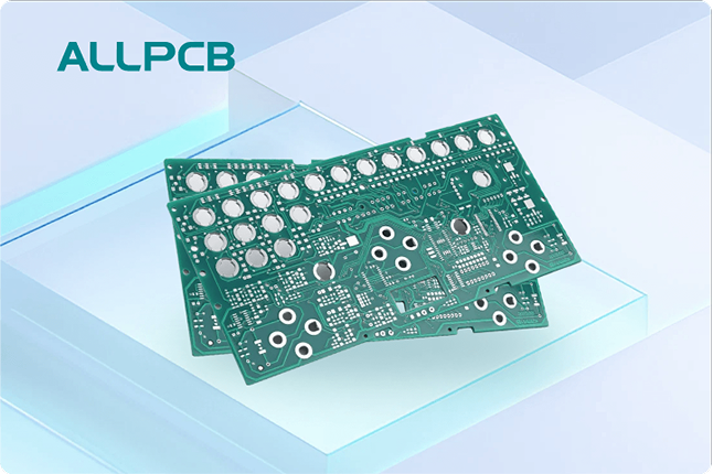
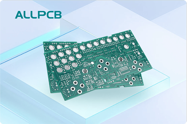
If you're looking for a copper pour design checklist to ensure reliable PCB design, you've come to the right place. Copper pour, a technique used to fill unused areas of a printed circuit board (PCB) with copper, is vital for improving electrical performance, thermal management, and signal integrity. In this comprehensive guide, we'll walk you through essential PCB design rules for copper pour, best practices, and guidelines to create dependable and high-performing boards. Whether you're a beginner or a seasoned engineer, this blog will provide actionable insights to elevate your PCB designs.
What Is Copper Pour and Why Does It Matter in PCB Design?
Copper pour, often referred to as copper flooding, is the process of filling empty spaces on a PCB layer with copper, typically connected to a ground or power net. This technique serves multiple purposes, including reducing electromagnetic interference (EMI), improving heat dissipation, and providing a stable reference plane for signals. When done correctly, copper pour enhances the reliability and performance of your PCB. However, improper implementation can lead to issues like signal crosstalk or manufacturing defects.
In this blog, we'll dive deep into copper pour best practices and provide a detailed checklist to ensure your designs are both reliable and efficient. By following these copper pour guidelines, you can avoid common pitfalls and achieve optimal results for your projects.
The Benefits of Copper Pour in PCB Design
Before we get into the checklist, let's explore why copper pour is a critical aspect of reliable PCB design. Here are some key advantages:
- Improved Signal Integrity: Copper pour creates a consistent reference plane, reducing impedance mismatches and signal reflections. For high-speed designs, this can lower noise levels significantly, ensuring signals travel at speeds up to 3 GHz or more without degradation.
- EMI Reduction: A well-designed copper pour connected to ground can act as a shield, minimizing electromagnetic interference. This is especially important in densely packed boards with multiple high-frequency components.
- Thermal Management: Copper has excellent thermal conductivity (approximately 401 W/m·K), allowing it to dissipate heat from components like power ICs. This helps prevent overheating and extends the lifespan of your PCB.
- Manufacturing Efficiency: Filling unused areas with copper reduces the amount of etching required during fabrication, leading to more uniform boards and potentially lower production costs.
With these benefits in mind, let's move on to the core of this guide: the copper pour design checklist.
The Copper Pour Design Checklist for Reliable PCBs
Creating a reliable PCB requires careful attention to detail when implementing copper pour. Below is a comprehensive checklist of PCB design rules for copper pour to help you achieve optimal results. Follow these copper pour guidelines to ensure your design is both functional and manufacturable.
1. Define the Purpose of Your Copper Pour
Start by determining the primary goal of your copper pour. Is it for grounding, power distribution, or thermal dissipation? Each purpose may require a different approach. For instance, a ground plane pour should connect to as many ground pins as possible to minimize noise, while a power plane pour might focus on delivering stable voltage (e.g., 3.3V or 5V) to specific components.
Clearly defining the purpose ensures that your copper pour serves its intended function without introducing unintended side effects like parasitic capacitance.
2. Choose the Right Layer for Copper Pour
Decide which layer of your PCB will host the copper pour. For multilayer boards, ground planes are often placed on internal layers to provide a stable reference for high-speed signals. In a 4-layer PCB, for example, the second layer is commonly dedicated to ground with a full copper pour, while the third layer might handle power distribution.
For single- or double-layer boards, copper pour on the top or bottom layer can still be effective but may require more careful routing to avoid interference with traces.
3. Set Appropriate Clearance Rules
Clearance rules define the minimum distance between the copper pour and other elements like traces, pads, and vias. Insufficient clearance can lead to short circuits or signal interference. A common guideline is to maintain a clearance of at least 0.2 mm (8 mils) between the copper pour and unrelated nets. For high-voltage designs, you might need to increase this to 0.5 mm (20 mils) or more to prevent arcing.
Ensure your design software enforces these clearance rules automatically to avoid errors during layout.
4. Connect Copper Pour to the Correct Net
Always connect your copper pour to the appropriate net, such as ground or power. A floating copper pour (one not connected to any net) can act as an antenna, picking up or radiating EMI and degrading performance. Use vias or direct connections to tie the pour to the desired net, and verify connectivity during the design review process.
For ground pours, consider using multiple vias (via stitching) to create low-impedance paths to the ground plane. This is especially important in high-frequency designs where return paths must be short to minimize loop inductance.
5. Avoid Creating Isolated Copper Islands
Isolated copper areas, or "islands," that are not connected to any net can cause manufacturing issues and increase EMI. During the design process, check for small, unconnected patches of copper and remove them or connect them to the main pour. Most PCB design tools have features to detect and highlight these isolated regions for easy correction.
6. Use Thermal Reliefs for Pads and Vias
When a copper pour connects directly to component pads or vias, it can act as a heat sink during soldering, making it difficult to achieve proper solder joints. To prevent this, use thermal reliefs—small gaps or spokes around pads that limit heat dissipation. A typical thermal relief might have four spokes, each 0.25 mm (10 mils) wide, connecting the pad to the pour.
This ensures better soldering results while maintaining electrical connectivity.
7. Manage Copper Pour in High-Speed Designs
In high-speed PCB designs, copper pour must be handled with extra care to avoid signal integrity issues. For signals operating above 100 MHz, ensure the copper pour does not create unintended return paths that could cause crosstalk. Keep high-speed traces away from the edges of the pour, and use via stitching to maintain a consistent ground reference.
Additionally, avoid placing copper pour under sensitive analog components like operational amplifiers, as it can introduce noise or parasitic capacitance.
8. Balance Copper Distribution for Manufacturing
Uneven copper distribution across a PCB can lead to warping during fabrication due to thermal stress. Aim for a balanced copper pour on both sides of the board, especially for double-sided or multilayer designs. If one layer has significantly more copper than another, consider adding dummy copper fills or adjusting the pour to achieve symmetry.
A good rule of thumb is to aim for at least 50-70% copper coverage on each layer to ensure uniform etching and plating.
9. Verify Copper Pour with Design Rule Checks (DRC)
Before finalizing your design, run a design rule check using your PCB design software. This process will identify potential issues like insufficient clearances, floating copper, or unconnected nets. Address any errors or warnings flagged by the DRC to ensure your copper pour adheres to manufacturing and performance standards.
10. Consider Thermal Expansion and Contraction
Copper expands and contracts with temperature changes, which can stress the PCB material if not accounted for. For boards operating in extreme environments (e.g., -40°C to 85°C), ensure the copper pour does not cover areas prone to mechanical stress, such as near mounting holes. Leave small gaps or use segmented pours in these regions to reduce the risk of cracking.
Copper Pour Best Practices for Optimal Results
Beyond the checklist, adopting these copper pour best practices will further enhance the reliability of your PCB designs:
- Simulate Before Fabrication: Use simulation tools to analyze the impact of copper pour on signal integrity and thermal performance. Tools like SPICE or electromagnetic simulators can predict issues before you send your design for manufacturing.
- Consult Manufacturer Guidelines: Different manufacturers may have specific requirements for copper pour, such as minimum clearance or maximum copper thickness (e.g., 1 oz/ft2 or 2 oz/ft2). Review these guidelines early in the design process.
- Iterate and Test: After completing your initial design, prototype the PCB and test it under real-world conditions. Measure parameters like EMI levels or thermal performance to validate your copper pour strategy.
Common Mistakes to Avoid with Copper Pour
Even with a solid checklist, mistakes can happen. Here are some common pitfalls to watch out for in your copper pour design:
- Overfilling Without Purpose: Adding copper pour without a clear objective can increase parasitic effects and complicate routing. Always have a specific goal in mind.
- Ignoring High-Density Areas: In densely populated boards, excessive copper pour can interfere with component placement. Prioritize space for traces and components first.
- Neglecting Via Placement: Poorly placed vias in a copper pour can create high-impedance paths, especially for ground connections. Strategically place vias to minimize resistance and inductance.
Conclusion: Building Reliable PCBs with Copper Pour
Implementing copper pour effectively is a cornerstone of reliable PCB design. By following the copper pour design checklist and adhering to best practices, you can enhance signal integrity, reduce EMI, and improve thermal management in your boards. Remember to define the purpose of your pour, set proper clearances, avoid isolated copper islands, and balance copper distribution for manufacturability.
With these copper pour guidelines in hand, you're well-equipped to create high-performing and dependable PCBs for any application. Keep iterating on your designs, simulate potential issues, and always stay updated on the latest PCB design rules for copper pour. Your attention to detail will pay off in the form of robust, reliable electronics.
By prioritizing these steps, you're not just designing a PCB—you're building a foundation for success in your electronic projects. Let this guide serve as your go-to resource for copper pour best practices and reliable PCB design.
 ALLPCB


