ALLPCB


The increasing demand for millimeter-wave and sub-terahertz applications has driven the development and production of new antennas, necessitating cost-effective and precise antenna measurement systems. Traditional RF and microwave anechoic chambers are often prohibitively expensive for many developers, leading to reliance on third-party facilities for antenna validation and acceptance testing. This results in high costs and long wait times. However, the high-frequency characteristics of millimeter-wave and sub-terahertz bands allow for smaller antenna apertures, making compact anechoic chambers viable for research, development, and production testing. This article focuses on near-field antenna measurement systems, discussing key considerations and the impact of probe antenna selection on measurement speed and data quality, with brief reference to compact range (indirect far-field) systems.
Compact Range vs. Near-Field Testing Systems
Compact range testing systems use large reflector antennas or antenna arrays to project plane-wave test signals onto the antenna under test (AUT). The transmit antenna remains stationary, while the AUT rotates in azimuth and elevation. If the transmit antenna generates a true plane wave, it effectively simulates a far-field source, despite being physically located in the near-field region. The power transmitted between the AUT and the transmit antenna is proportional to the AUT¡¯s far-field gain, enabling direct measurement of antenna parameters in a compact chamber. However, designing and constructing compact range systems is challenging, and their measurement accuracy can be limited by factors that become harder to control at millimeter-wave and sub-terahertz frequencies.
Near-field testing systems offer an alternative, using smaller microwave chambers to measure antenna performance. Unlike compact range systems, near-field systems employ a mobile probe antenna to measure the transmission response between the probe and the AUT at various positions within the AUT¡¯s near-field region. The collected data points form a synthetic aperture, capturing the AUT¡¯s near-field radiation pattern.
Near-Field Scanning Configurations
Many near-field systems use a planar scanning surface, which is ideal for measuring directional antennas with low sidelobes. The AUT¡¯s directional pattern allows all significant radiation parameters to be captured within a limited scanning area.
For antennas with lower gain or higher sidelobes, spherical or cylindrical scanning surfaces are more suitable. Spherical near-field systems typically use low-gain probe antennas that approximate omnidirectional behavior at angles close to the aperture. Low-gain probes offer greater flexibility in angular positioning relative to the AUT and often eliminate the need for probe correction during data processing.
To capture all significant near-field energy from the AUT, the scanning surface must be sufficiently large. The required scanning area and type are typically determined by the AUT¡¯s sidelobe offset positions. As a rule of thumb for planar and cylindrical scans, the scanning height should approximately equal the sum of the AUT height, the probe antenna height, and twice the distance between the AUT and probe multiplied by the tangent of the maximum measurement angle from the main lobe perspective. For example, if both the probe and AUT have a height of 1 cm (aperture of 2¡Á2 cm), the distance between them is 20 cm, and the maximum measurement angle is ¡À15 degrees, the recommended scanning height is ¡À2¡Á[1+1+20¡Átan(15¡ã)] cm, or approximately ¡À15 cm.
Far-Field Transformation
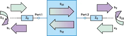
The amplitude and phase of the transmission path between the probe antenna and the AUT are critical for mathematically transforming near-field data into far-field antenna patterns. A dedicated vector network analyzer typically performs these measurements. For each measurement, the probe¡¯s position must be within the wavelength range of the operating frequency to ensure accurate data collection.