ALLPCB


Overview
In electronic PCB design, resistors are among the most common and important components. This article examines typical resistor application circuits used across electronic devices and provides brief analysis of their functions.
1. Current-limiting resistor
Used to limit the maximum current flowing in a circuit.
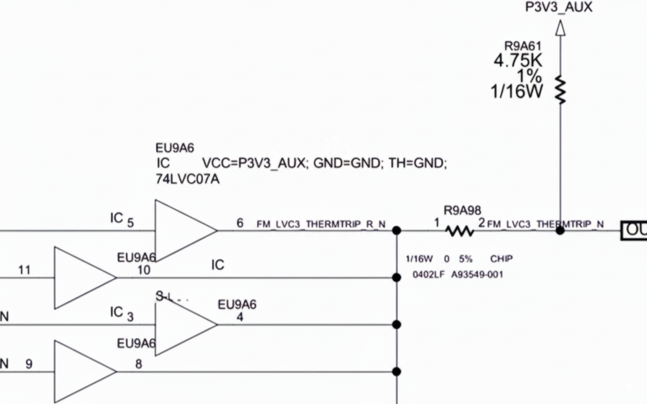
2. Pull-up and pull-down resistors
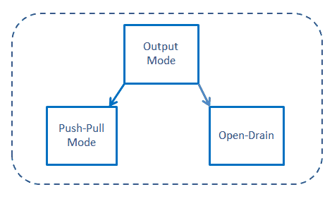
Some chip output pins are open-collector or open-drain and require pull-up or pull-down resistors.
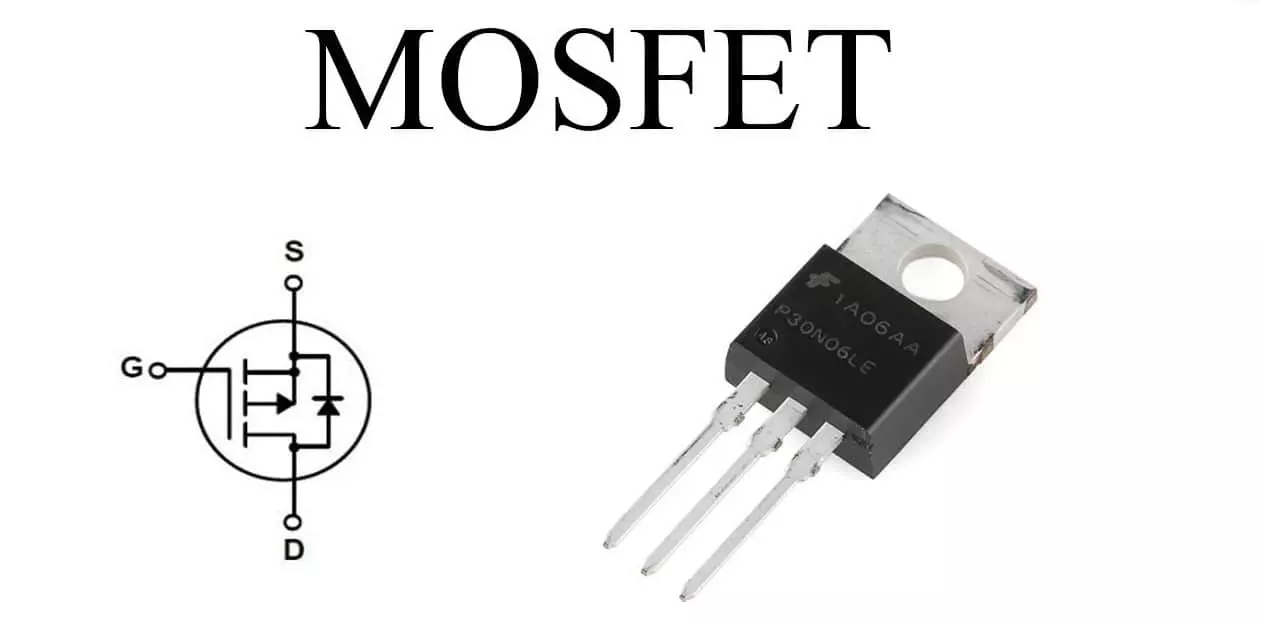
Pull resistors are also commonly applied to MOSFET gates or to configuration/strap pins on certain chips.
3. Series resistor
Adding a series resistor on high-speed lines can serve as termination and reduce signal reflections.
4. RC delay circuit
Resistor-capacitor networks create timing delays or filter signals, commonly used for reset delays, debouncing, or simple timing functions.
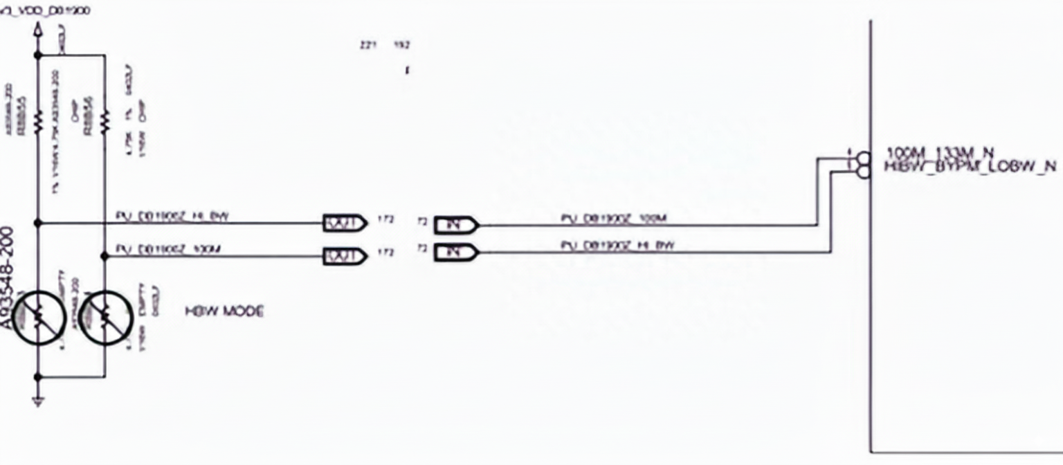
5. Voltage divider
Voltage dividers generate required reference voltages or scale signals for ADCs and other inputs.
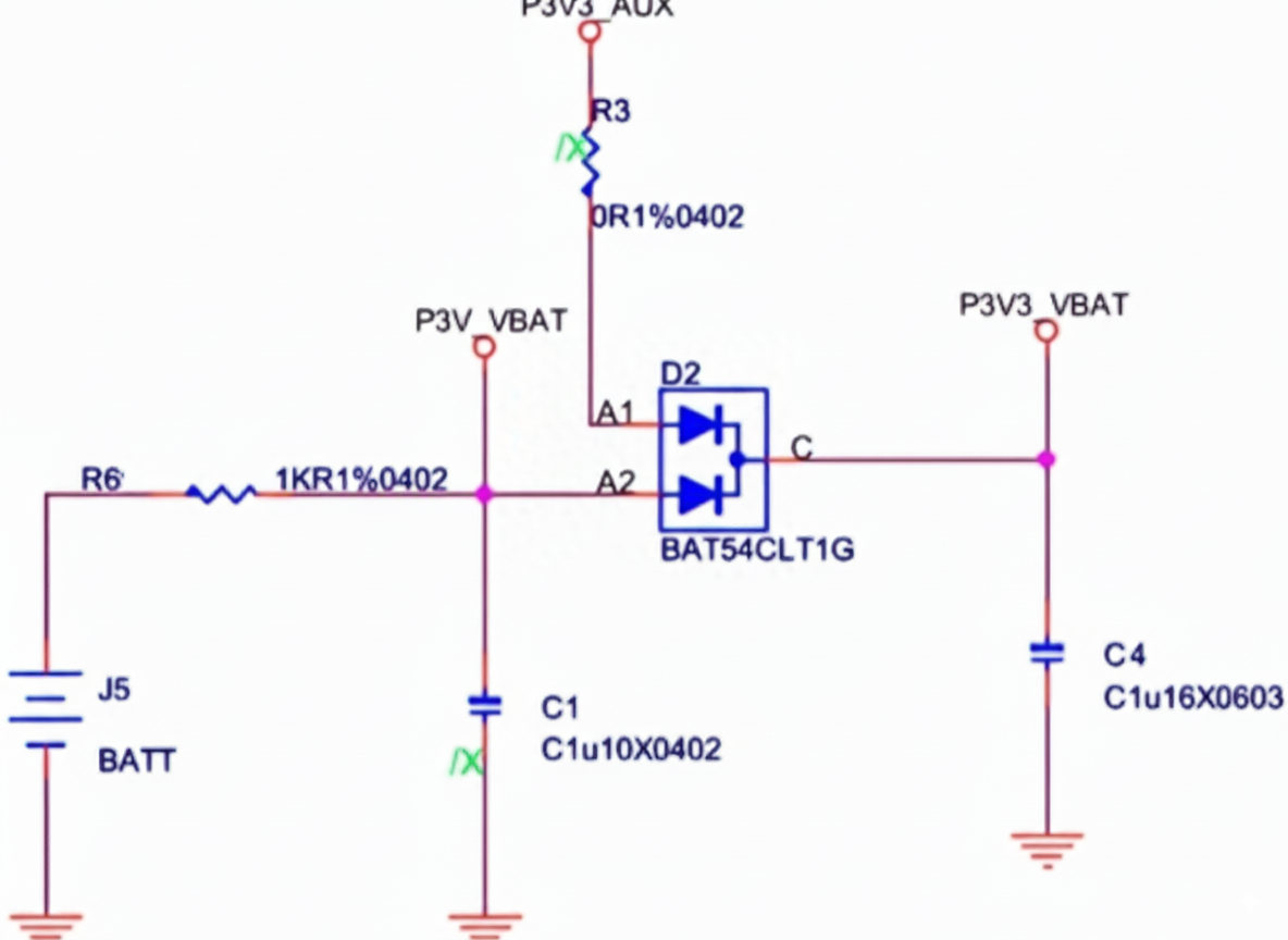
6. Precision bias resistors
Precision resistors used to provide bias or reference voltages for internal circuits of a chip.
7. 0-ohm resistor as jumper/debug node
0-ohm resistors are often used as jumpers to reserve test or debug nodes, to configure options, or to allow easy rework.
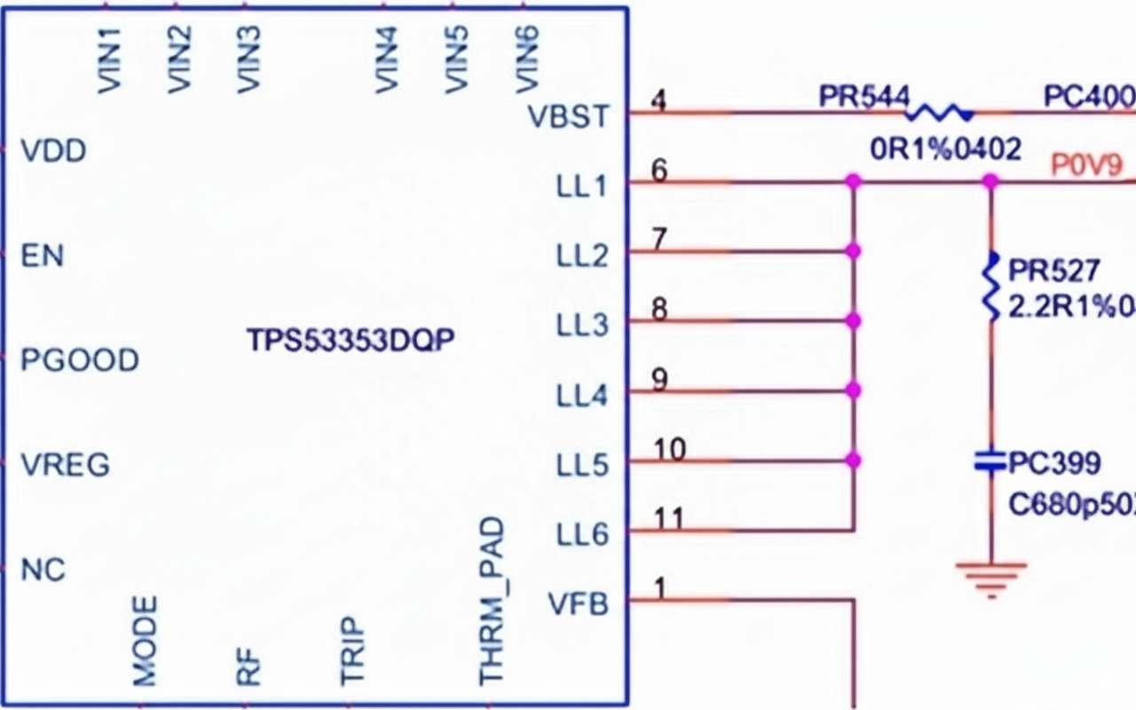
8. Pure power-load resistor
Some DC-DC converter outputs drive loads with very high equivalent resistance, which can produce long discharge times during power-down and potentially cause power-sequencing issues. A resistor is often added at the output to provide a defined load and shorten discharge time.
9. Precision shunt resistor for current sensing
Low-value precision resistors are used as current-sense shunts to measure current by converting it to a small voltage drop readable by measurement circuits or ADCs.