ALLPCB


Overview
A rotary encoder is a position sensor that converts the angular position of a knob into digital signals used to determine rotation direction. Because of their robustness and suitability for digital control, rotary encoders are widely used in robotics, CNC machines, and printers.
Encoder Types and Operation
Rotary encoders are available in two types: absolute and incremental. Absolute encoders provide the exact angular position in degrees, while incremental encoders report how many increments the shaft has moved.
Inside an incremental encoder is a slotted disk connected to a common ground pin C and two contact pins A and B. When the knob is rotated, pins A and B contact the common ground C in a specific sequence depending on rotation direction.
When they contact ground they produce signals. Because one pin contacts before the other, the signals are phase-shifted by 90 degrees; this is called quadrature encoding.
For clockwise rotation the A pin contacts first, then B. For counterclockwise rotation B contacts first, then A. By tracking when each pin connects to or disconnects from ground, you can determine rotation direction. A common method is to observe the state of B when A changes state.
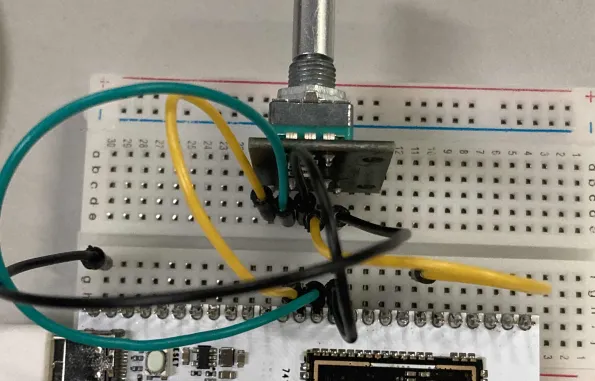
Circuit
The example wiring used in this article is shown below.
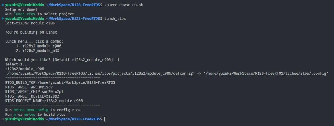
1. Load Configuration
Introduction
The development board used here is the R128-Devkit. For applications running on the C906 core, select the r128s2_module_c906 configuration.
$ source envsetup.sh $ lunch_rtos 1
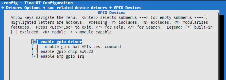
2. GPIO Driver
Enable
In mrtos_menuconfig, enable the following drivers:
Drivers Options ---> soc related device drivers ---> GPIO devices ---> [*] enable GPIO driver [*] enable GPIO hal APIs Test command
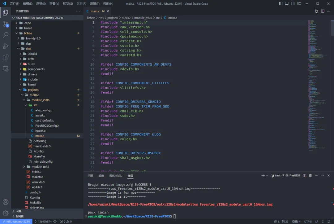
3. Programming
Introduction
Open your preferred editor and modify the file at:
lichee/rtos/projects/r128s2/module_c906/src/main.c
4. Headers
Includes
#include <hal_gpio.h>
5. Using GPIO
Pin configuration
1. Configure GPIO pull-up/pull-down
Use:
hal_gpio_set_pull (gpio_pin_t pin, gpio_pull_status_t pull);
Example: set PA25 to default pull-up:
hal_gpio_set_pull(GPIOA(25), GPIO_PULL_UP);
2. Configure GPIO direction
Use:
hal_gpio_set_direction (gpio_pin_t pin, gpio_direction_t direction);
Example: set as input:
hal_gpio_set_direction(GPIOA(25), GPIO_DIRECTION_INPUT);
3. Configure GPIO MUX function
GPIO pins usually support multiple functions. Select the required function with:
hal_gpio_pinmux_set_function (gpio_pin_t pin, gpio_muxsel_t function_index);
Example: set to GPIO input mode (GPIO_MUXSEL_IN):
hal_gpio_pinmux_set_function(GPIOA(25), GPIO_MUXSEL_IN);
4. Read GPIO level
Use:
int hal_gpio_get_data (gpio_pin_t pin, gpio_data_t *data);
Example:
gpio_data_t gpio_data; hal_gpio_get_data(GPIOA(25), &gpio_data);
5. Request and configure interrupts
Use hal_gpio_to_irq to obtain an IRQ number, hal_gpio_irq_request to bind an interrupt handler, and hal_gpio_irq_enable to enable the interrupt. Example sequence:
// store IRQ number uint32_t irq_clk; // request IRQ number ret = hal_gpio_to_irq(ENC_CLK, &irq_clk); if (ret < 0){ printf("gpio to irq error, irq num:%d error num: %d", irq_clk, ret); } // bind interrupt handler ret = hal_gpio_irq_request(irq_clk, gpio_irq_encode, IRQ_TYPE_EDGE_BOTH, NULL); if (ret < 0){ printf("request irq error, irq num:%d error num: %d", irq_clk, ret); } // enable IRQ ret = hal_gpio_irq_enable(irq_clk); if (ret < 0){ printf("request irq error, error num: %d", ret); }
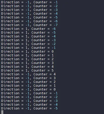
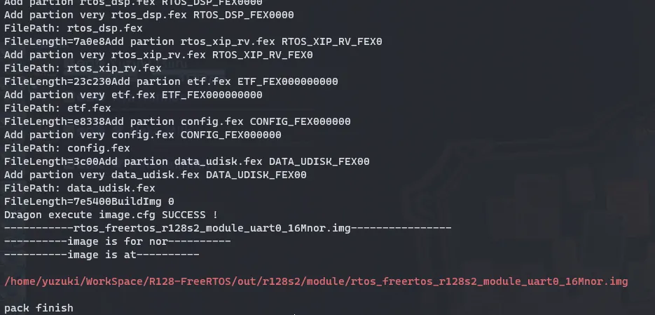
6. Complete Example Code and Result
#include <stdio.h> #include <stdint.h> #include <string.h> #include <unistd.h> #include "interrupt.h" #include <portmacro.h> #include <cli_console.h> #include <aw_version.h> #include <hal_time.h> #include <hal_gpio.h> #include "FreeRTOS.h" #include "task.h" #include "tinatest.h" extern int amp_init(void); // Define rotary encoder pins #define ENC_CLK GPIOA(24) #define ENC_DT GPIOA(25) #define ENC_SW GPIOA(29) // Related global storage variables int encode_counter = 0; int encode_current_clk; int encode_lask_clk; int current_dir = 0; // Encoder interrupt handler static hal_irqreturn_t gpio_irq_encode(void *data){ // Get pin level states gpio_data_t clk_value = GPIO_DATA_LOW; gpio_data_t dt_value = GPIO_DATA_LOW; hal_gpio_get_data(ENC_DT, &dt_value); hal_gpio_get_data(ENC_CLK, &clk_value); // Determine current data state encode_current_clk = clk_value; if (encode_current_clk != encode_lask_clk && encode_current_clk == 1){ // Determine rotation direction if (dt_value != encode_current_clk) { // Clockwise encode_counter ++; current_dir = 1; } else { // Counterclockwise encode_counter --; current_dir = -1; } printf("Direction = %d, Counter = %d", current_dir, encode_counter); } // Refresh current state encode_lask_clk = encode_current_clk; return 0; } void cpu0_app_entry(void *param){ int ret = 0; // Initialize system resources amp_init(); // A24 -> CLK, A25 -> DT, A29 -> SW hal_gpio_set_pull(ENC_CLK, GPIO_PULL_DOWN_DISABLED); hal_gpio_set_direction(ENC_CLK, GPIO_DIRECTION_INPUT); hal_gpio_pinmux_set_function(ENC_CLK, GPIO_MUXSEL_IN); // Get initial encoder CLK state gpio_data_t clk_data; hal_gpio_get_data(ENC_CLK, &clk_data); encode_lask_clk = clk_data; hal_gpio_set_pull(ENC_DT, GPIO_PULL_DOWN_DISABLED); hal_gpio_set_direction(ENC_DT, GPIO_DIRECTION_INPUT); hal_gpio_pinmux_set_function(ENC_DT, GPIO_MUXSEL_IN); // Store CLK and DT IRQ numbers uint32_t irq_clk, irq_dt; // Request ENC_CLK IRQ, edge-triggered ret = hal_gpio_to_irq(ENC_CLK, &irq_clk); if (ret < 0){ printf("gpio to irq error, irq num:%d error num: %d", irq_clk, ret); } // Bind interrupt handler ret = hal_gpio_irq_request(irq_clk, gpio_irq_encode, IRQ_TYPE_EDGE_BOTH, NULL); if (ret < 0){ printf("request irq error, irq num:%d error num: %d", irq_clk, ret); } // Enable IRQ ret = hal_gpio_irq_enable(irq_clk); if (ret < 0){ printf("request irq error, error num: %d", ret); } // Request ENC_DT IRQ, edge-triggered ret = hal_gpio_to_irq(ENC_DT, &irq_dt); if (ret < 0){ printf("gpio to irq error, irq num:%d error num: %d", irq_dt, ret); } // Bind interrupt handler ret = hal_gpio_irq_request(irq_dt, gpio_irq_encode, IRQ_TYPE_EDGE_BOTH, NULL); if (ret < 0){ printf("request irq error, irq num:%d error num: %d", irq_dt, ret); } // Enable IRQ ret = hal_gpio_irq_enable(irq_dt); if (ret < 0){ printf("request irq error, error num: %d", ret); } vTaskDelete(NULL); }