ALLPCB


1. Background and requirements
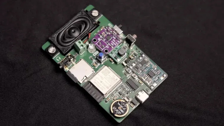
As the smart toy market advances, interactive children's devices are evolving from simple light-and-sound feedback to more conversational behavior. The WT3000A-M6 module offers millisecond-level response latency, multimodal interaction capabilities, and child-focused safety features, making it suitable for smart toy applications. This document provides a PCB implementation path for typical smart toy hardware, such as educational robots, story players, and interactive dolls.
2. System architecture
2.1 Overall framework
Adopt a dual-core heterogeneous architecture:
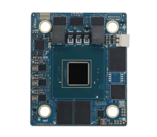
- Main controller: STM32 H750 as the system MCU, communicating with WT3000A-M6 via SPI interface
- Voice processing unit: WT3000A-M6 performs wake word detection, noise reduction, and local command recognition
- Expansion interfaces: Reserved GPIOs to control motors/lights, PWM interface to drive expressive displays
2.2 Signal flow
Microphone array -> module audio input -> voice processing -> local commands -> main controller executes actions; cloud interaction -> WebSocket upload -> TTS playback
3. Key circuit design
3.1 Audio capture system
Design approach:
- Use a 4-microphone ring array, 15 mm spacing, to achieve 360° pickup
- Front-end amplification: TI OPA1678, adjustable gain range 40–60 dB
- Configure a second-order Butterworth filter with a 16 kHz cutoff frequency
Feedback sampling circuit:
- Install a 1% precision sampling resistor at the speaker output
- Use AD A4077 to construct a feedback loop to eliminate howling
Layout notes:
- Microphone trace length differences < 5 mm, matching error ±0.1 mm for equal length
- Analog ground and digital ground connected at a single point via a 0 Ω resistor
3.2 Wireless communication
Bluetooth/WiFi integrated design:
- Shared PCB inverted-F antenna, size 20 x 5 mm
- RF front end: use SKY66421 front-end module
- Configure a pi-type matching network and tune with a Smith chart to 2.4 GHz
- Isolation: keep Bluetooth and WiFi modules > 15 mm apart
- Use metal shielding cans to separate RF areas
3.3 Power management
Three-tier power architecture:
- Main power: 3.7 V Li-ion input, TPS61088 boost to 5 V
- Module power: 3.3 V LDO: TPS7A4701 (noise 3 uVrms)
- Dynamic voltage regulation: switch between 2.8 V and 3.6 V according to operating mode
- Peripheral power:
- Motor drive: SY8089 DC-DC with 2 A output capability
- LED strips: PT4115 constant-current driver IC
- Low-power design:
- Standby current < 50 uA (voice wake mode)
- Use TPS22916 load switches for modular power control
4. PCB layout optimization
4.1 Stackup
Use a 6-layer board:
- Layer 1: signal layer (key analog traces)
- Layer 2: ground plane
- Layer 3: power plane
- Layer 4: digital signal layer
- Layer 5: RF dedicated layer
- Layer 6: bottom layer (high-current paths)
4.2 Key area placement
Voice processing area:
- Place WT3000A-M6 near the center, within 20 mm of the microphones
- Reserve a 10 x 10 mm thermal copper area
RF area:
- Maintain a 3 mm keep-out around the antenna
- Impedance control: 50 Ω ± 10%
Motor drive area:
- Use 2 oz copper for high current paths
- Provide TVS array protection (ESD 5Z3.3T1G)
4.3 Signal integrity
- Voice I2S bus: length matching error < 5 mil, spacing following 3W rule
- Digital signal lines: add 33 Ω series resistors for termination
- Clock signals: guard with ground, length < 50 mm
5. Child safety design
5.1 Hardware safety mechanisms
- Over-temperature protection: NTC thermistor + MAX6613 monitoring chip
- Tamper detection: use FPC flexible connectors for removable parts
- Electromagnetic safety: comply with EN 62115 toy safety standards
5.2 Acoustic safety control
- Limit output sound pressure level to below 75 dB
- Use an automatic level control (ALC) circuit:
- Use TS472 headphone amplifier
- Dynamic range compression ratio 4:1
6. Development support
6.1 Reference design kit
Provide a core board (50 x 30 mm) plus expansion board architecture including:
- Typical toy control interfaces (servos/PWM LED/touch sensing)
- Offline voice training tools (supports Mandarin child voice optimization)
6.2 Rapid production recommendations
- Stencil design suggestions: module pad aperture ratio 1:0.9
- Use Type 5 solder powder (20–38 μm)
- Test fixtures: acoustic test chamber (compliant with IEC 60268-21)
- RF test system automatic calibration procedures
7. Typical application example
Educational robot implementation:
Functional features:
- Wake word: "Xiao Zhi Teacher"
- Local recognition of 100+ teaching commands (for example, "spell check")
- Cloud connection to ChatGPT for Q&A interactions
Performance targets:
- Wake response time < 200 ms
- Continuous operation: 8 hours battery life
- Operating temperature range: -20°C to 60°C
8. Cost optimization strategies
BOM optimization:
- Use 0402 package components to reduce area by about 30%
- Select HSCODE-8L no-clean solder paste to lower processing cost
Production optimization:
- Support panelization (2 x 2 panel)
- Automated ICT solutions with > 95% test coverage