ALLPCB


Overview
For an ideal quadrature mixer, the local oscillator (LO) would produce only a positive or only a negative frequency component. In practice, IQ mismatch between the I and Q paths causes both positive and negative frequency components to appear, with one component typically weaker than the other.
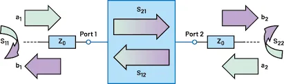
System model
Below we analyze this phenomenon using formula-level reasoning to show how IQ mismatch leads to image interference. Consider a block diagram where the transmitter uses an ideal quadrature mixer while the receiver quadrature mixer exhibits IQ mismatch. The gain mismatch and phase mismatch between the I and Q branches are denoted by △G and △φ, respectively. Losses between the transmitter baseband and the receiver baseband are not considered.
Signal expressions
The transmitted signal can be expressed as follows:
(formula omitted in source)
After demodulation by the receiver quadrature mixer, the signal is given by:
(formula omitted in source)
A factor j is included in the formula because the signal is assumed to have already been processed in baseband.
Rearrangement and result
To obtain the relationship between the desired signal and the image interference, the above expression must be rearranged.
After reorganization, the result can be written as:
(formula omitted in source)
In other words, gain and phase mismatches in the IQ paths generate image interference, and it is possible to derive the relationship between the image rejection ratio and the gain and phase mismatches.
Conclusion
IQ gain and phase mismatch in a zero-IF receiver produce an image component in addition to the desired baseband signal. The image suppression depends on the magnitude of the gain and phase errors and can be derived from the expressions above.