ALLPCB


Overview
A duplexer is a main component used with frequency-separated duplex radios and repeater stations. Its function is to isolate transmit and receive signals so that receiving and transmitting can operate simultaneously. It is typically implemented using two sets of band-stop (notch) filters at different frequencies to prevent the local transmit signal from coupling into the receiver.
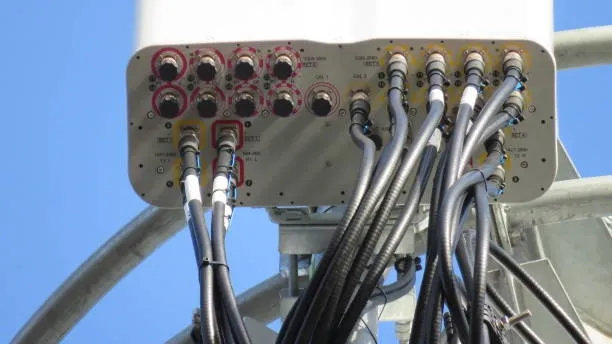
Typical Structure
A duplexer commonly contains six notch filters tuned to the transmit and receive frequencies. Filters on the receive side are tuned to the transmit frequency to prevent transmit power from entering the receiver; filters on the transmit side are tuned to the receive frequency. Major components include a coupler, an isolator, filters, and the antenna. The coupler separates or combines transmit and receive paths, the isolator prevents mutual interference between transmitter and receiver, and the filters select the desired frequency bands and route them to the appropriate path. These components are connected via printed circuit boards, microstrip lines, transmission lines, or other suitable interconnects to form the complete duplexer.
How to Measure Duplexer Isolation
Duplexer isolation quantifies how well the transmit and receive channels are isolated from each other. Common measurement methods include:
-
Power-measurement method: Inject test signals with known power into the transmit and receive ports and measure the signal power appearing at the opposite port. The ratio between the measured power at the non-intended port and the input power is used to calculate isolation. This method evaluates isolation performance at different power levels.
-
Spectrum-analysis method: Apply test signals at different frequencies to the transmit and receive ports and use a spectrum analyzer to measure the power of signals appearing on the receive channel. Comparing received power across frequencies yields the isolation profile versus frequency. This method is suitable for evaluating isolation across the operational band.
-
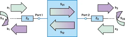
Reflection-coefficient method: Send test signals at various frequencies into the duplexer and measure the reflected signals or S11/S21 parameters from the receive port. Comparing reflection or transmission coefficients across frequency provides information about the duplexer’s frequency response and isolation performance.
Specific measurement procedures may vary depending on the duplexer design and the test equipment used.
Relevant Technical Specifications
Key specifications related to duplexer isolation include:
-
Isolation: The level, typically expressed in decibels (dB), indicating how much the transmit channel signal is suppressed in the receive channel. Higher isolation means better separation between transmit and receive channels.
-
Insertion loss: The power loss experienced by a signal passing through the duplexer on the intended path. Lower insertion loss indicates less signal power is lost during transmission through the duplexer and is typically expressed in dB.
-
Out-of-band leakage: The extent to which transmit-channel energy unintentionally appears in the receive channel outside the intended band. Lower out-of-band leakage indicates reduced interference from the transmit channel into the receive channel.
These parameters are important for evaluating and selecting duplexers for radio systems.