 ALLPCB


01
What is an inductor?
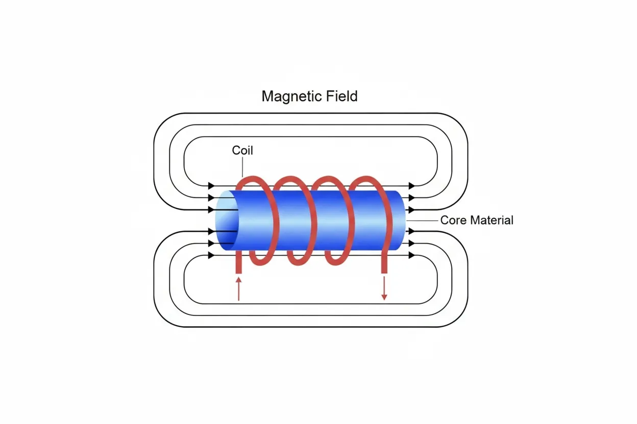
An inductor is a circuit element that stores energy in its magnetic field. It stores electrical energy as magnetic energy and then returns it to the circuit to regulate current. As current increases, the magnetic field strengthens. Figure 1 shows the inductor model.
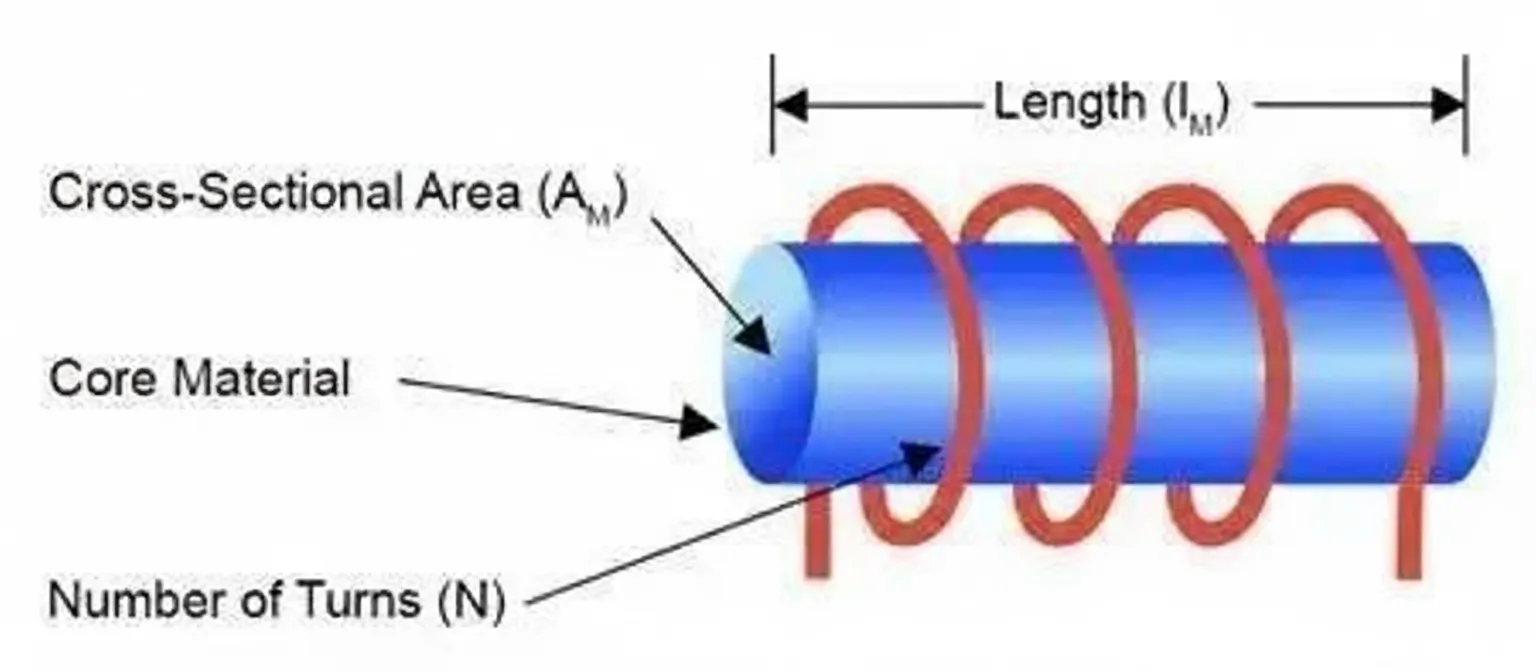
Inductors are formed by winding insulated wire into coils. Coils can have different shapes and sizes and can be wound on different core materials. The inductance depends on factors such as the number of turns, core size, and permeability. Figure 2 shows key inductor parameters.
Below we describe common inductor parameters in detail.
02
Inductor parameters
Permeability
Permeability is a material's response to magnetic flux and indicates how much flux can pass through an inductor under an applied electromagnetic field.
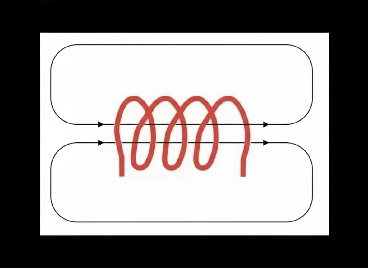
Flux density depends on the core permeability and dimensions. Figure 3 shows a coil without a magnetic core.
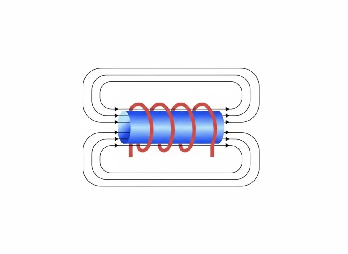
An air-core coil has a constant relative permeability (μr (air)) approximately equal to 1. Figure 4 shows an inductor with a magnetic core; the magnetic field is enhanced when a core is present.
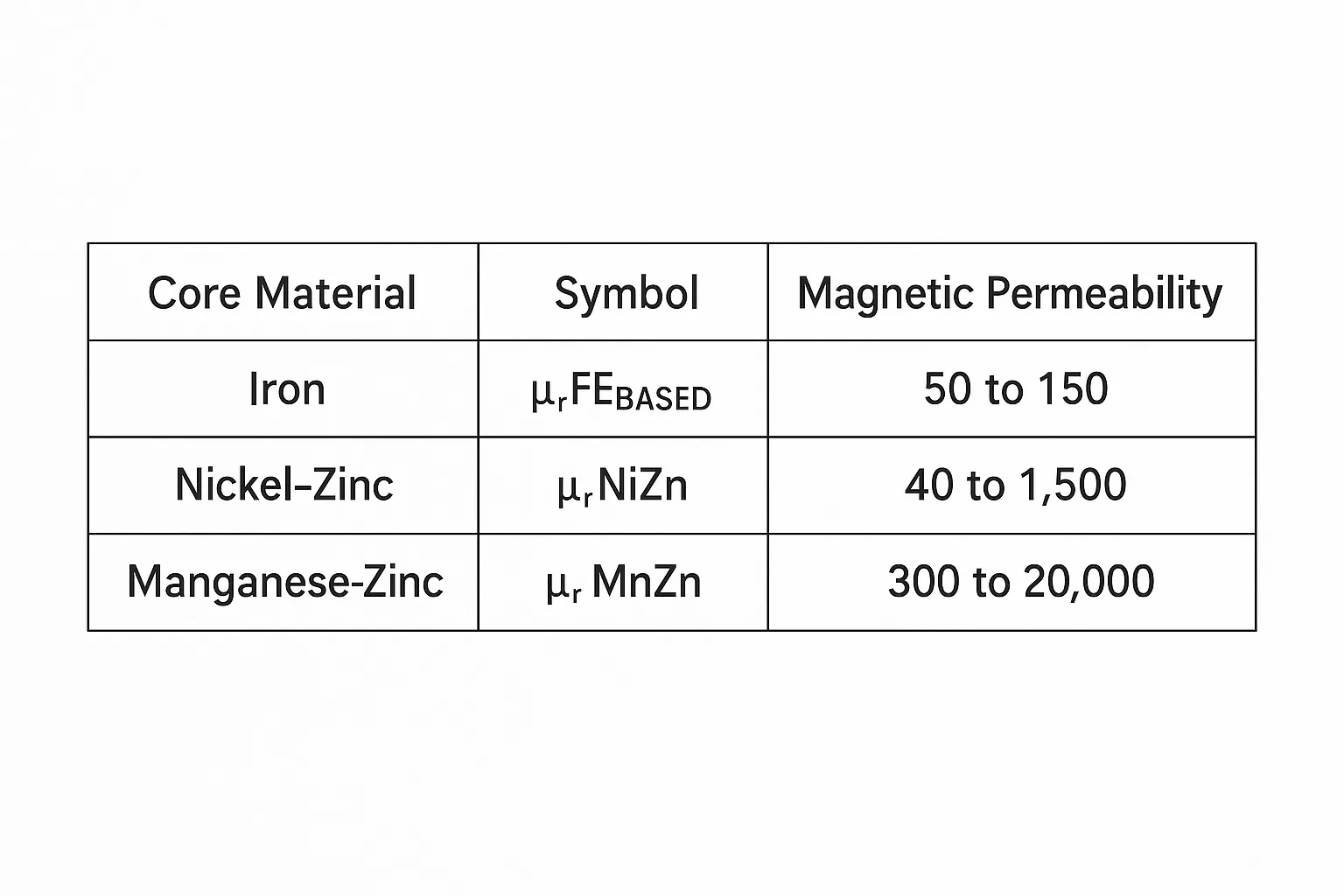
Typical relative permeabilities vary by core material. Table 1 lists permeabilities for three different core materials.
Inductance (L)
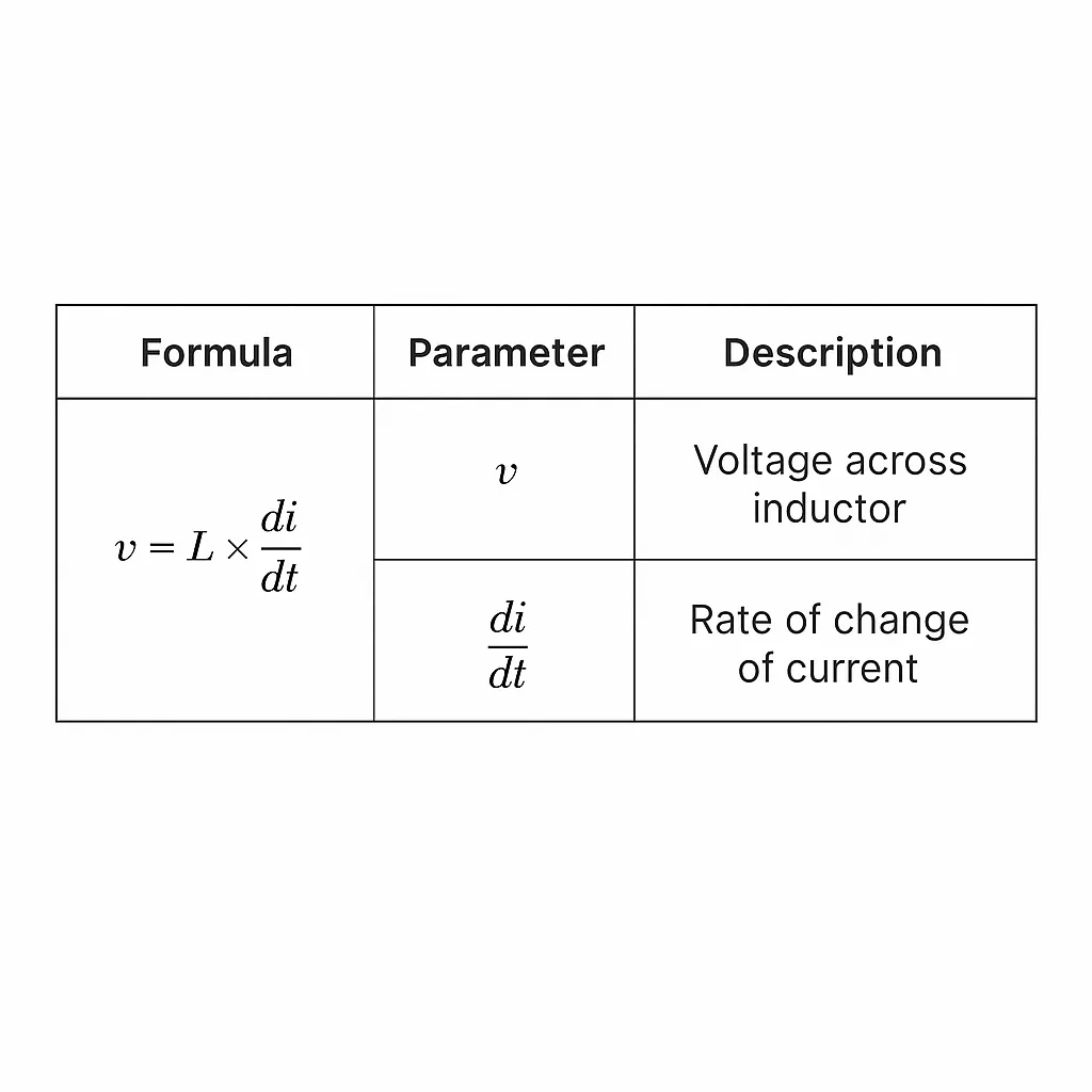
Inductance quantifies the ability of an inductor to store induced electrical energy as magnetic energy. When a switching input voltage drives an inductor, the inductor supplies a steady DC current to the output load. Table 2 shows the relationship between current and inductor voltage. The voltage across the inductor is proportional to the rate of change of current over time.
First, determine the inductance range required for the design. Note that inductance is not constant across all operating conditions; it changes with frequency. Applications with higher switching frequencies require special consideration. Inductor manufacturers typically test inductors at 100 kHz to 500 kHz because most DC/DC converters operate within this range.
Resistance (R)
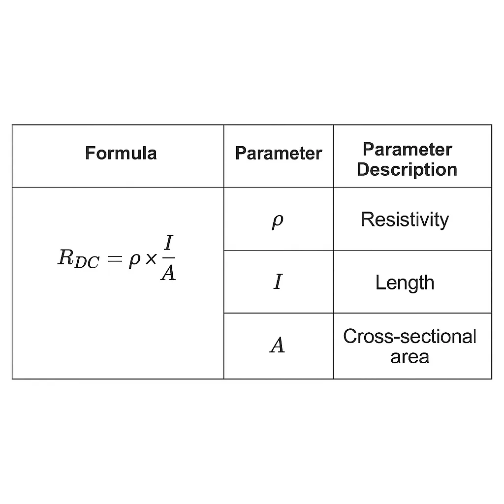
The DC resistance of the inductor windings causes heat dissipation and affects efficiency. Total copper loss includes RDC loss and RAC loss. RDC is frequency independent and constant; RAC depends on frequency. Table 3 shows how to calculate RDC.
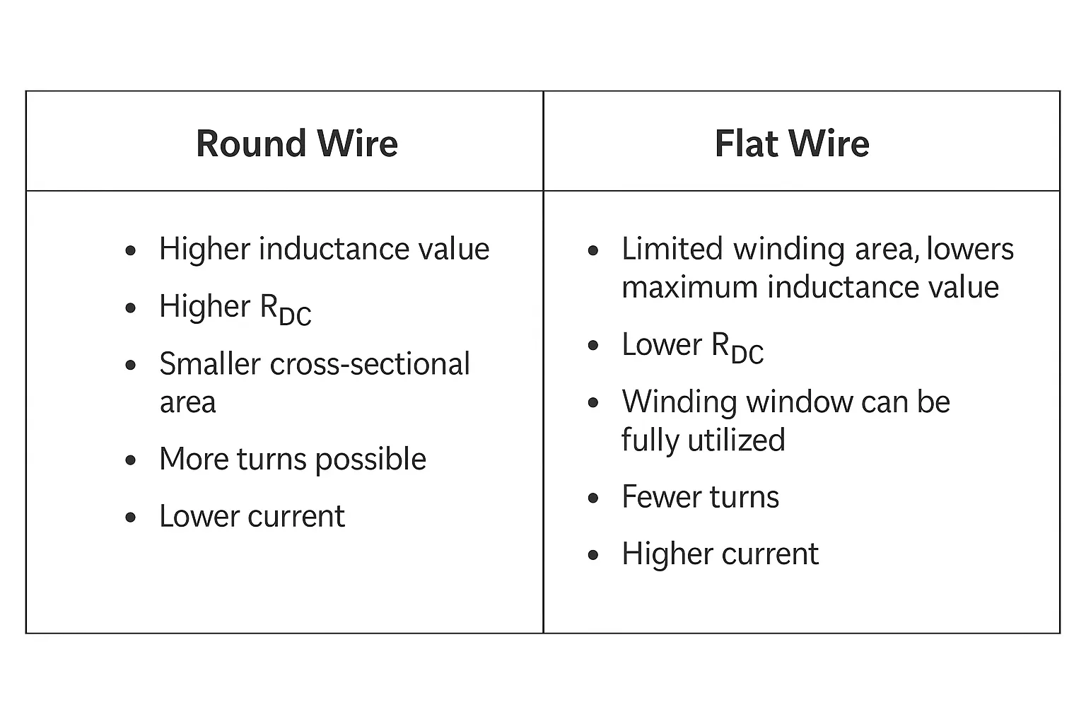
The only way to reduce copper loss is to increase conductor area by using thicker wire or flat wire. Flat wire allows more complete use of the winding window and yields lower RDC.
Table 4 compares characteristics of round and flat wire.
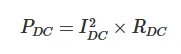
Use equation (1) to estimate the DC copper loss (RDC):
AC copper loss (PAC) depends on PAC, which is caused by proximity effect and skin effect driven by frequency. PAC increases with frequency.
Core loss
Ferromagnetic materials typically satisfy the magnetic requirements for inductor cores. Relative permeabilities for core materials range from about 50 to 20,000 depending on material. When a magnetic field is applied, magnetic domains align; without a field, domain orientations are random. Changes in magnetic energy cause core loss. As domains grow and shrink, some domains become pinned in the crystal structure. When pinned domains rotate free, energy is dissipated as heat.
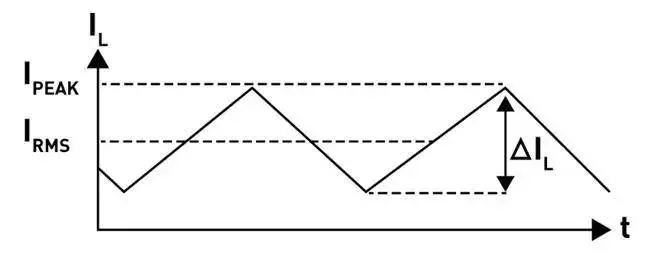
Ripple current (ΔIL)
Ripple current (ΔIL) is the change in current during one switching cycle. An inductor may not perform properly if operation exceeds its peak current range. Ripple current is typically designed to be in the 30% to 40% range of IRMS. Figure 5 shows the inductor current waveform.
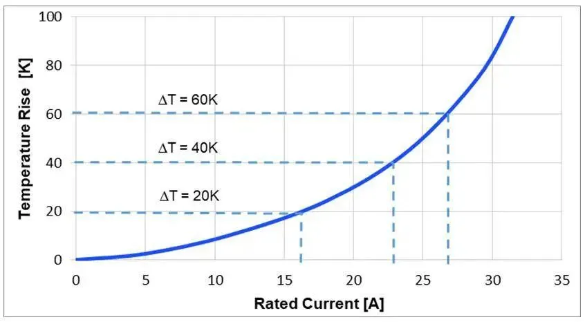
Rated current (IDC, IRMS)
Rated current is the DC current that causes a specified temperature rise in the inductor. Temperature rise (ΔT) is not standardized but is commonly between 20 K and 40 K. Rated current is measured at ambient temperature and is typically provided in the inductor datasheet as the expected operating current for the intended application. For applications with higher ambient temperature, designers should choose inductors with higher allowable self-heating. Figure 6 shows the relationship between temperature rise and rated current.
Operating temperature (TOP) in an application is determined by ambient temperature (TAMB) and the inductor's self-heating (ΔT). TOP can be estimated using equation (2):
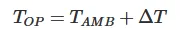
Given rated current is the best method to estimate inductor temperature rise. Temperature rise is also affected by circuit design, PCB layout, proximity to other components, and trace dimensions and thickness. Excessive AC loss in the core and windings can also generate additional heat. To reduce self-heating, choose an inductor with a larger package size.
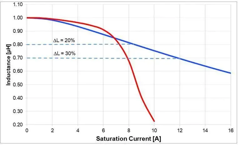
Saturation current (ISAT)
The saturation current rating indicates the DC current an inductor can support before its inductance drops by a specified percentage. Each inductor has a reference percentage for inductance drop. Manufacturers typically specify this percentage between 20% and 35%, which can complicate direct comparisons. Datasheets often provide a curve showing how inductance changes with DC current. Use this curve to evaluate the inductance range and its response to DC current. DC saturation current depends on temperature, the magnetic material, and core structure. Different core structures and materials affect ISAT. Ferrite cores are common and exhibit a hard saturation characteristic (see Figure 7). It is critical to avoid operating an inductor beyond its specified inductance drop point, because beyond that point inductance falls rapidly and functionality degrades. Molded composite inductors show more gradual inductance decline with temperature and exhibit a soft saturation characteristic, offering designers more flexibility and a wider operating range. Figure 7 shows two saturation curves: the blue curve is a typical soft saturation example for molded composite inductors; the red curve is a typical hard saturation example for NiZn/MnZn drum-core inductors.
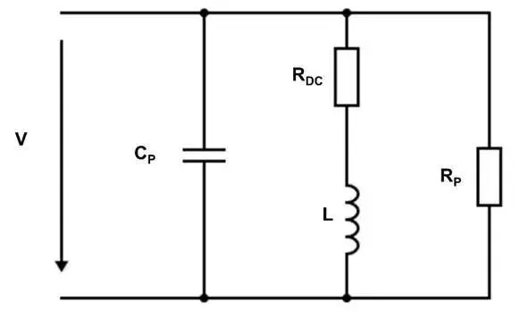
Self-resonant frequency and impedance
The self-resonant frequency (fR) of an inductor is the lowest frequency at which the inductor and its parasitic capacitance resonate. Below the resonant frequency, impedance reaches a peak and the effective inductance is the expected value. Figure 8 shows the inductor circuit model.
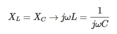
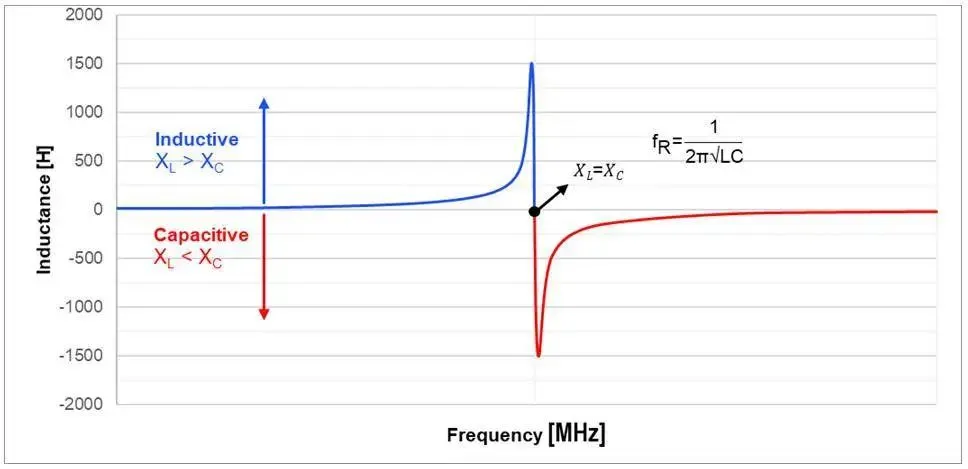
Inductors exhibit inductive behavior below the resonant frequency, as shown by the blue curve in Figure 9, with impedance rising as frequency increases. At resonance, the capacitive reactance (XC) equals the inductive reactance (XL). Resonant frequency can be estimated using equation (3):
Above the resonant frequency, as shown by the red curve in Figure 9, the inductor behaves more like a capacitor and impedance decreases. Beyond this point the inductor will not behave as expected. Figure 9 shows the relationship between inductance and frequency.
Choosing a compact inductor with the right tradeoffs
With a basic understanding of each parameter in an inductor datasheet, selecting a suitable inductor becomes straightforward. A deeper understanding of the details behind each parameter enables better selection for DC/DC converter applications and helps predict system performance under different conditions.
03
Conclusion
There are many types of inductors for different applications, and choosing the most suitable one can be challenging. For example, a larger inductance can reduce DC loss and improve efficiency, but such inductors are physically larger and run hotter. No single inductor is ideal for all purposes. Understanding each parameter and the relationships between parameters helps designers determine whether an inductor is suitable for a specific DC/DC application.


