 ALLPCB


Bulk current injection (BCI) immunity testing is particularly well-suited for evaluating the RF disturbance immunity of electronic equipment with complex cable harnesses in confined spaces. Consequently, it is a standard test method referenced in product standards for automotive electronics, military equipment, and avionics, where the electromagnetic environment is harsh and reliability and safety requirements are extremely high.
BCI testing presents a significant challenge for the immunity design of electronic devices, as it involves injecting high-power RF energy into all cables across a wide frequency band. Furthermore, the testing, diagnostic analysis, and solution validation often rely on resources from commercial labs, which can have a major impact on R&D costs. Therefore, the risks associated with BCI compliance should not be underestimated, especially for development teams lacking BCI design experience and effective tools.
By applying and extending the fundamental principles of BCI, a method for in-house pre-testing and diagnostic analysis can be established. This approach allows EMC engineers to build rapid BCI pre-testing and diagnostic capabilities at their own facilities early in the development cycle, effectively reducing R&D risks.
BCI Test Principles
The basic principle of BCI is to use a current probe to couple and inject common-mode current onto a device's cable harness, simulating the injection of RF energy from the electromagnetic environment. BCI testing is typically performed using the substitution method, where the power delivered to the injection probe is a predetermined level calibrated in a 100? system. A block diagram is shown below.
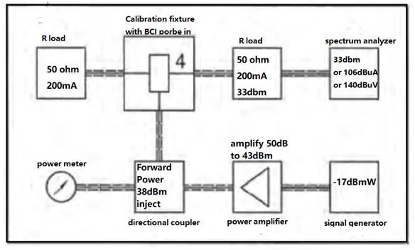
Let's analyze the maximum BCI immunity test level of 106 dBµA, which corresponds to 200 mA. Since the test system impedance is 100? (compared to the 300? system for IEC 61000-4-6 conducted immunity), the total power injected into the system is:
P = I² * R = (0.2 A)² * 100? = 4W = 36 dBm
The actual power injected towards the Equipment Under Test (EUT) port is:
P/2 = 2W = 33 dBm
Due to the coupling efficiency of BCI injection probes (typically -7 dB to -20 dB) and additional losses from attenuators and directional couplers in the amplifier's output path (around -6 dB), a standard BCI test requires an amplifier with a power output approaching 50 dBm. Generally, an amplifier of 200W or more is needed to perform a full-frequency band BCI immunity test at the 200 mA level.
An R&D Pre-test Method for High-Current BCI
Since a standard BCI test laboratory requires significant investment in equipment and maintenance, it is often beyond the reach of small and medium-sized enterprises. A pre-testing method that can achieve a 200 mA injection level with a smaller fixed investment offers a practical solution. However, compared to a standard lab, this approach involves several simplifications based on practical constraints:
- Share a test bench with a CISPR 25 emissions setup instead of building a dedicated shielded room.
- Use a smaller 100W RF power amplifier with a 3 dB output attenuator.
- Use a closed-loop current injection probe instead of a clamp-on type to achieve higher coupling efficiency.
- Perform calibration and testing manually to reduce investment in control equipment and software.
This pre-test method's success hinges on a specially designed current injection probe. By improving the coupling efficiency and reducing impedance matching losses, the required amplifier power can be significantly lowered.
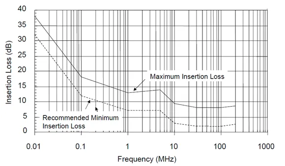
As seen in the standard curve above, the coupling capability of current injection probes is weaker at lower frequencies, necessitating higher injection power. The proposed pre-test method uses a large-aperture, closed-loop injection probe to improve low-frequency coupling and reduce the amplifier power requirement.
Because the magnetic core inside a closed-loop injection probe has no air gap, its coupling capability is superior to that of an open, clamp-on type across the entire frequency band. This advantage is particularly pronounced below 500 kHz. Additionally, the complete internal core can handle more power than the semi-circular core of an open clamp. The trade-off is that a closed-loop probe requires a larger inner diameter for the cable harness to pass through.
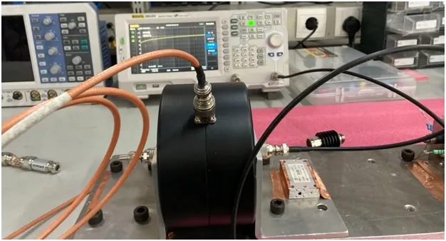
The figure above shows a closed-loop injection probe with a 90mm inner diameter. Insertion loss measurements, performed with a spectrum analyzer with a tracking generator and a calibration fixture, demonstrate that the closed-loop probe offers superior coupling bandwidth, flatness, and efficiency compared to an open-clamp probe. Using a closed-loop probe can significantly reduce the maximum power required from the amplifier.
In addition to the critical current injection probe and power amplifier, an in-house BCI pre-test setup requires several basic components: a metal ground reference plane, an RF signal generator with AM/FM capabilities, 100W 3/6 dB attenuators, a spectrum analyzer for monitoring RF signals, an oscilloscope for observing waveforms, a calibration fixture, and auxiliary equipment such as power supplies, cooling fans, coaxial cables, and signal attenuators. After assembling this system and performing a 200 mA injection calibration, a list of corresponding signal source output levels is generated. The open-loop substitution method BCI test can then be conducted by setting the signal generator to these levels. Since the capital investment for the site, amplifier, and probe is much lower than for a standard lab, and no control software is needed, the overall cost of this pre-test system is minimal, making it accessible for R&D teams. Experience shows that results from this system have a high correlation with those from standard test labs, making it perfectly suitable for development-phase testing.
Diagnostic & Analysis Methods for BCI Failures
When a BCI test failure occurs, the available information—the sensitive cable, frequency band, current level, and failure mode—is necessary but often insufficient for resolving the problem. For unshielded or unfiltered electronic devices, solving a BCI issue depends entirely on identifying the interference path and the specific circuit being affected. This requires more direct and efficient diagnostic tools.
Since BCI is merely a means of RF injection, the true goal is to deliver RF energy to the sensitive components. We can replicate BCI failures by injecting RF energy directly. Two recommended methods for this are direct injection and voltage probe injection. These techniques allow diagnostic efforts to move to the PCB and circuit level, transforming the analysis from a "black-box" to a "white-box" approach.
In IEC 61000-4-6 conducted immunity testing, the direct injection method is used to inject current onto cable shields via a 100? coaxial resistor (a 50? to 150? adapter). By adapting this method, BCI diagnostics can use direct RF injection, through a DC-blocking capacitor, not only on shields but also directly into circuits. Since the effective power for a 200 mA BCI injection is about 2W, a small, general-purpose 5W wideband amplifier is sufficient for direct injection requirements.
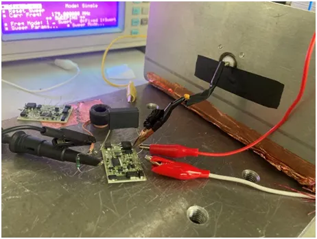
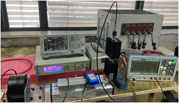
The figure above shows a setup for analyzing a BCI immunity problem on a small circuit. The 5W RF energy from the amplifier passes through a 3 dB attenuator (reducing power to 2.5W) and a DC-blocking capacitor, allowing it to be safely injected into a low-voltage circuit. By simultaneously observing the circuit's performance with auxiliary equipment, engineers can evaluate its immunity. This method is highly effective for in-depth analysis of a hardware circuit's BCI performance, enabling the discovery of potential weaknesses and direct validation of proposed solutions.
For larger circuits or systems, direct injection using a common-mode voltage probe at cable ports and within circuits is recommended. The EMC standard CISPR 16-1-2 introduces a voltage probe for measuring conducted common-mode voltage in special cases, but its high common-mode impedance of 1500? makes it unsuitable for injection. By designing lower-impedance voltage probes, RF energy injection becomes feasible, providing a new approach for analyzing and solving conducted emission and immunity problems.
| Probe Type | CR Network | Insertion Loss (IL) | Impedance | Voltage Rating |
|---|---|---|---|---|
| 150?, 3 dB Type | 22nF + 3dB | 150kHz-1000MHz 3dB | 150? / 50? | 2 kV |
| 60?, 10 dB Type | 22nF + 10dB | 150kHz-1000MHz 10dB | 60? / 50? | 2 kV |
The two types of RF voltage probes in the table, with different common-mode impedances and attenuation coefficients, are suitable for various immunity diagnostics. They can be used for conducted immunity injection, BCI injection, or radiated immunity RF injection, as well as for diagnosing conducted emissions problems.
On a limited budget, it is even possible to forgo the large injection probe and high-power amplifier. Using a voltage probe and a small 5W wideband amplifier to directly inject RF energy at the I/O port circuitry can be sufficient for a 200 mA BCI immunity assessment. This pre-test method is fast, convenient, and low-cost. It plays a crucial role in the early analysis, identification, and resolution of BCI problems, though it does require a higher level of equipment operation and diagnostic skill from the EMC engineer.
Solving immunity problems always depends on finding the final sensitive circuit that is being disturbed. Direct RF injection provides solid, empirical test data, preventing vague or incomplete solutions. A basic workflow for using direct injection and voltage probes for BCI problem diagnosis is as follows:
- Identify the BCI failure and sensitive frequency points during pre-testing.
- Confirm the failure and its sensitivity level.
- Use a current probe to inject onto the cable harness and determine the sensitive cable, ruling out non-sensitive cables to make a preliminary path assessment.
- Use a voltage probe for RF injection at the ports to precisely locate the sensitive port circuit and position.
- Use the direct injection method to probe sensitive circuits on the PCB, find a solution, and quickly verify its effectiveness.
- Verify the effectiveness of the solution at the cable and system levels.
The pre-testing and diagnostic methods proposed for BCI immunity can also be adapted for conducted and radiated immunity testing and analysis. They are highly effective for EMC engineers seeking to control EMC risks and design efficiently during the R&D process.


