 ALLPCB


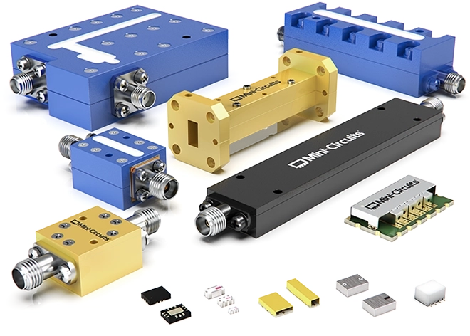
Filters are essential components in RF systems, primarily used for frequency selection—passing desired signal frequencies while rejecting unwanted interference.
Filters are widely used in the RF, intermediate frequency (IF), and baseband sections of a receiver. While digital filters have begun to replace analog filters in the baseband and even IF sections with the advancement of digital technology, RF filters remain irreplaceable. Therefore, filters are a critical component in any RF system.
Filter Classifications
Filters can be classified in several ways:
- By frequency response characteristics: Low-pass, high-pass, band-pass, and band-stop filters.
- By implementation technology: LC filters, surface acoustic wave (SAW)/bulk acoustic wave (BAW) filters, helical filters, dielectric filters, cavity filters, high-temperature superconducting filters, and planar structure filters.
- By frequency response function: Butterworth, Chebyshev, generalized Chebyshev, Gaussian, Bessel, and elliptic (Cauer) filters.
These classifications describe different filter characteristics based on various performance requirements.
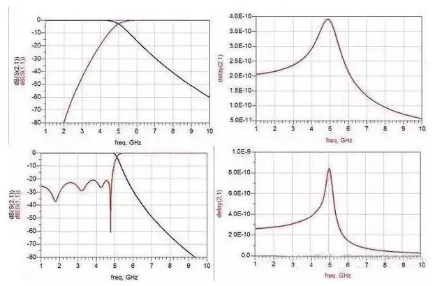
When selecting a filter, the first step is to determine whether a low-pass, high-pass, band-pass, or band-stop type is needed. The frequency response characteristics of these types are illustrated below.
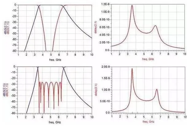
Butterworth and Chebyshev band-pass filters
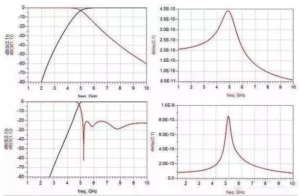
Butterworth and Chebyshev high-pass filters
Common Filter Applications
The most commonly used types are low-pass and band-pass filters. Low-pass filters are widely used for image rejection in mixers and harmonic suppression in frequency sources. Band-pass filters are common in receiver front-ends for signal selection, in transmitter power amplifiers for spurious emission suppression, and in frequency sources for spurious rejection.
As functional components in microwave RF systems, filters have corresponding electrical performance specifications to describe their capabilities. Different applications have different requirements for these electrical characteristics.
Related Reading: How Filters, Common-Mode Chokes and Ferrite Suppress EMI
Key Filter Specifications
The technical specifications describing a filter's electrical performance include:
- Order (Number of Stages)
- Absolute/Relative Bandwidth
- Cutoff Frequency
- VSWR (Voltage Standing Wave Ratio)
- Out-of-Band Rejection
- Ripple
- Insertion Loss
- Passband Flatness
- Phase Linearity
- Absolute Group Delay
- Group Delay Variation
- Power Handling Capacity
- Phase Consistency
- Amplitude Consistency
- Operating Temperature Range
Below is an explanation of each of these performance specifications.
Order (Number of Stages)
For high-pass and low-pass filters, the order is the total number of capacitors and inductors. For band-pass filters, it's the total number of parallel resonators. For band-stop filters, it's the total count of series and parallel resonators.
Absolute/Relative Bandwidth
Typically used for band-pass filters, this metric indicates the range of signal frequencies that can pass through the filter. Relative bandwidth is the absolute bandwidth expressed as a percentage of the center frequency.
Cutoff Frequency
This term is generally for high-pass and low-pass filters. For a low-pass filter, it defines the upper frequency limit of the passband. For a high-pass filter, it defines the lower frequency limit.
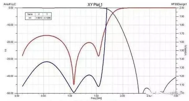
VSWR (Voltage Standing Wave Ratio)
Measured as S11 on a vector network analyzer (VNA), VSWR indicates how well the filter's port impedance is matched to the system impedance. It represents the amount of input signal reflected back to the source.
Insertion Loss
Insertion loss represents the energy lost as a signal passes through the filter, i.e., the energy dissipated by the filter.
Related Reading: Filter Capacitors in EMC Design
Passband Flatness
The absolute difference between the maximum and minimum insertion loss within the filter's passband. It characterizes how uniformly the filter attenuates signals at different frequencies within the passband.
Out-of-Band Rejection
The amount of attenuation outside the filter's passband. It measures the filter's ability to reject unwanted frequencies.
Ripple
The variation (difference between peaks and valleys) in the S21 response curve within the passband.
Phase Linearity
The difference between the filter's phase response and the phase of an ideal transmission line with a group delay equal to the filter's delay at the center frequency. It characterizes the filter's dispersion properties.
Absolute Group Delay
The time it takes for a signal to travel from the input port to the output port within the passband.
Group Delay Variation
The difference between the maximum and minimum absolute group delay across the passband. This also characterizes the filter's dispersion.
Power Handling Capacity
The maximum power of a passband signal that can be input to the filter.
Phase Consistency
The variation in transmission phase between different units of the same filter model from the same production batch. It measures the unit-to-unit consistency.
Amplitude Consistency
The variation in insertion loss between different units of the same filter model from the same production batch. This also characterizes batch-to-batch consistency.
Filters are indispensable components in wireless communication systems. There are many types of filters, each with different performance characteristics. Therefore, selecting the right filter requires a comprehensive consideration of the application environment and performance needs.
When key filter specifications are not fully defined, it is helpful to start by clarifying requirements such as physical size, insertion loss, required rejection at specific frequencies, and power handling capacity. These basic parameters are often sufficient to determine the most suitable type of filter for an application.


