ALLPCB


In the fast-paced world of server technology, high-current PCB layouts for server motherboards face intense thermal challenges. As data centers and enterprise systems demand more power and performance, managing heat becomes critical to ensure reliability and efficiency. So, how can you optimize thermal management for these complex designs? The answer lies in strategic layout planning, advanced simulation tools, effective heat sink placement, airflow optimization, and leveraging multi-layer stackups for thermal performance.
In this comprehensive guide, we'll dive deep into advanced thermal management techniques tailored for high-current PCB server motherboards. Whether you're an engineer designing cutting-edge systems or a tech enthusiast seeking to understand thermal dynamics, this blog will provide actionable insights to keep your designs cool under pressure. Let's explore the key strategies for thermal simulation in PCB design, heat sink placement, optimizing airflow in high-density PCBs, and enhancing thermal performance with multi-layer stackups.
Why Thermal Management Matters for High-Current PCB Server Motherboards
Server motherboards are the backbone of modern computing infrastructure, handling massive data loads and high-power components like CPUs, GPUs, and voltage regulators. These high-current PCB layouts often operate under extreme conditions, dissipating significant amounts of heat—sometimes exceeding 100 watts per component. Without proper thermal management, this heat can lead to reduced performance, component failure, and even system downtime.
Effective thermal management ensures that temperatures remain within safe limits, typically below 85°C for most components, to maintain reliability. It also extends the lifespan of the hardware and prevents costly failures in mission-critical applications. By focusing on thermal simulation, strategic heat sink placement, and airflow optimization, you can tackle the unique challenges of high-density server designs.
Key Challenges in Thermal Management for Server Motherboards
Before diving into solutions, it's important to understand the specific thermal challenges faced by high-current PCB layouts in server motherboards:
- High Power Density: Modern server designs pack multiple high-power components into tight spaces, creating hotspots that can exceed 120°C without proper cooling.
- Limited Space: The compact nature of server racks restricts airflow and heat dissipation options, making traditional cooling methods less effective.
- Complex Multi-Layer Designs: Server motherboards often use 12 or more layers, complicating heat distribution and requiring careful stackup planning.
- Continuous Operation: Servers often run 24/7, leaving little time for components to cool down, which increases thermal stress over time.
Addressing these challenges requires a multi-faceted approach, combining design techniques with advanced tools. Let's break down the strategies for optimizing thermal performance.
Thermal Simulation in PCB Design: Predicting and Preventing Hotspots
One of the most powerful tools for managing heat in high-current PCB server motherboards is thermal simulation in PCB design. This process involves using software to model how heat flows through a board, identifying potential hotspots before physical prototypes are built. By simulating worst-case scenarios—such as full CPU load or peak power draw—you can predict temperature distributions and adjust your design early.
Thermal simulation tools can analyze factors like component placement, copper thickness, and via structures to estimate temperatures. For instance, a simulation might reveal that a voltage regulator module (VRM) reaches 110°C under load, prompting you to add thermal vias or reposition the component. These tools often integrate with layout software, allowing real-time analysis during the design phase.
Steps for Effective Thermal Simulation:
- Define power dissipation values for each component (e.g., a CPU might dissipate 150W).
- Input material properties, such as the thermal conductivity of copper (approximately 400 W/m·K) and FR-4 substrate (around 0.3 W/m·K).
- Simulate airflow conditions, whether natural convection or forced air cooling with fans.
- Analyze results to identify areas exceeding safe temperature thresholds, typically 85-90°C for most ICs.
- Iterate the design by adjusting layouts or adding cooling solutions until temperatures are within limits.
By leveraging thermal simulation in PCB design, you save time and resources, avoiding costly redesigns after prototyping. Many modern design platforms offer built-in simulation features to streamline this process.
Heat Sink Placement on PCBs: Maximizing Cooling Efficiency
Heat sinks are a cornerstone of thermal management for high-current PCB server motherboards. These passive cooling devices absorb and dissipate heat from critical components like processors and power modules. However, their effectiveness depends heavily on proper heat sink placement on the PCB.
Best Practices for Heat Sink Placement:
- Position Near Hotspots: Place heat sinks directly over or adjacent to high-power components. For example, a CPU dissipating 120W should have a dedicated heat sink with a thermal interface material (TIM) to ensure efficient heat transfer.
- Consider Airflow Direction: Align heat sink fins with the direction of airflow in the server chassis to maximize cooling. Misaligned fins can reduce efficiency by up to 30%.
- Avoid Crowding: Ensure there’s enough space around the heat sink for air to circulate. Overlapping heat sinks or placing them too close to tall components can trap heat.
- Use Thermal Pads or Paste: Apply a high-quality thermal compound between the component and heat sink to reduce thermal resistance, often lowering temperatures by 5-10°C.
Additionally, consider the heat sink’s material and design. Aluminum heat sinks with a thermal conductivity of around 200 W/m·K are common due to their cost-effectiveness, while copper options (400 W/m·K) offer superior performance for extreme cases. The size and fin density should also match the component’s heat output and available space.
Optimizing Airflow in High-Density PCBs: Enhancing Cooling Performance
In high-density PCBs like those used in server motherboards, optimizing airflow is essential to prevent heat buildup. Poor airflow can create stagnant hot zones, raising temperatures by 20°C or more in critical areas. Since server racks often have constrained environments, strategic design is key to ensuring cool air reaches hot components and warm air is efficiently expelled.
Tips for Optimizing Airflow in High-Density PCBs:
- Component Spacing: Arrange components to avoid blocking airflow paths. For instance, place taller components like capacitors downstream of airflow to prevent turbulence around heat sinks.
- Fan Placement: Position fans to create a consistent airflow direction, typically front-to-back in server chassis, delivering cool air over heat-generating areas.
- Ventilation Openings: Design the PCB and enclosure with vents or cutouts to allow hot air to escape, reducing internal temperatures by up to 15%.
- CFD Analysis: Use Computational Fluid Dynamics (CFD) tools to simulate airflow patterns and identify bottlenecks. Adjusting fan speeds or vent sizes based on CFD results can improve cooling efficiency.
Optimizing airflow in high-density PCBs often requires balancing cooling needs with space constraints. In some designs, forced air cooling with fans rated for 50-100 CFM (cubic feet per minute) is necessary to handle heat loads exceeding 200W across the board.
Multi-Layer PCB Stackup for Thermal Performance: Distributing Heat Effectively
Server motherboards often rely on multi-layer PCB stackups, sometimes with 12 or more layers, to handle complex routing and high-current demands. While these designs are necessary for signal integrity and power delivery, they also impact thermal performance. A well-planned stackup can distribute heat evenly, preventing localized hotspots that degrade components.
Strategies for Multi-Layer PCB Stackup Thermal Performance:
- Dedicated Power Planes: Use thick copper planes (2-3 oz/ft2) for power distribution. These planes act as heat spreaders, conducting heat away from components with high current draw, such as VRMs handling 50A or more.
- Thermal Vias: Incorporate arrays of thermal vias under hot components to transfer heat to inner layers or the opposite side of the board. A grid of vias with 0.3mm diameter can reduce local temperatures by 10-15°C.
- Layer Symmetry: Design the stackup with balanced copper distribution to avoid warping due to uneven thermal expansion. For example, mirror power and ground planes on opposite sides of the board.
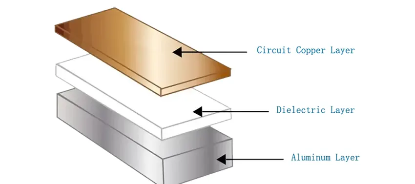
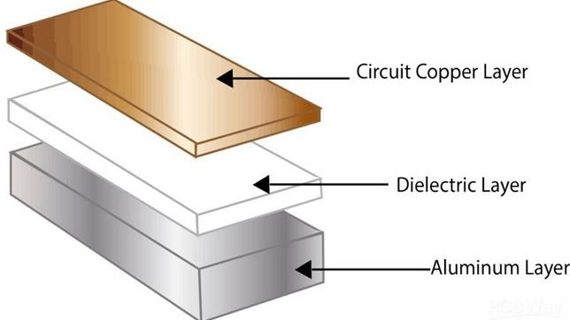
- Material Selection: Choose substrates with higher thermal conductivity, such as FR-4 variants with 0.5 W/m·K or metal-core PCBs for extreme cases, to improve heat dissipation.
By focusing on multi-layer PCB stackup for thermal performance, you create a robust foundation for heat management. Combining this with thermal simulation ensures that heat is evenly spread across the board, protecting sensitive components from thermal stress.
Additional Thermal Management Techniques for High-Current Designs
Beyond the core strategies discussed, several additional techniques can further enhance thermal management in high-current PCB server motherboards:
- Copper Pour Areas: Maximize copper coverage on surface layers to act as a heat spreader, especially near high-power components. A solid copper pour can lower local temperatures by 5-8°C.
- Active Cooling Solutions: For extreme heat loads, consider liquid cooling or Peltier devices alongside traditional heat sinks and fans. Liquid cooling can handle heat dissipation exceeding 300W in compact spaces.
- Component Derating: Operate components below their maximum ratings to reduce heat output. For example, running a VRM at 80% of its 100A capacity can significantly lower its operating temperature.
These methods, when combined with the primary strategies of simulation, heat sink placement, airflow optimization, and stackup design, provide a comprehensive approach to thermal management.
Conclusion: Building Cooler, More Reliable Server Motherboards
Thermal management is a critical factor in designing high-current PCB server motherboards that deliver consistent performance under demanding conditions. By leveraging thermal simulation in PCB design, optimizing heat sink placement, enhancing airflow in high-density PCBs, and carefully planning multi-layer PCB stackups for thermal performance, you can tackle even the toughest thermal challenges.
Start with simulation to predict and prevent hotspots, strategically place heat sinks for maximum cooling, ensure proper airflow to avoid heat buildup, and design stackups that distribute heat evenly. These steps not only protect your hardware but also improve system reliability and efficiency, ensuring your server designs meet the needs of modern data centers.
With the right tools and techniques, you can master advanced thermal management and create server motherboards that stay cool under pressure. Keep these strategies in mind for your next project, and watch your designs thrive in even the most heat-intensive environments.