 ALLPCB


Are you new to designing printed circuit boards (PCBs) for video processing applications? If so, you’re in the right place. This beginner’s guide will walk you through the essentials of video PCB design, from basic concepts to actionable steps and simple projects to get started. Whether you're searching for video PCB basics, a video PCB tutorial, or a video PCB design guide for beginners, this post covers it all with practical tips and clear explanations.
Video processing PCBs are the backbone of devices like cameras, video recorders, streaming hardware, and display systems. Designing them requires attention to signal integrity, power management, and component selection. In this detailed guide, we’ll break down the video PCB design steps and even suggest simple video PCB projects to help you build your skills.
What Is Video Processing PCB Design?
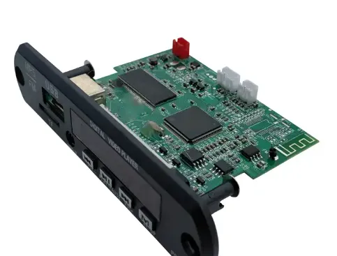
Video processing PCB design refers to creating circuit boards that handle video signals for input, processing, or output. These boards are used in devices that capture, encode, decode, or display video content. Unlike general-purpose PCBs, video processing boards must manage high-speed signals, minimize noise, and ensure reliable performance under demanding conditions.
For beginners, understanding video PCB basics starts with recognizing the unique challenges. Video signals often operate at high frequencies (up to several gigahertz for HD or 4K video), requiring careful layout to prevent signal degradation. Additionally, power delivery must be stable to avoid interference with sensitive analog and digital components.
Why Is Video PCB Design Important?
The quality of a video processing PCB directly impacts the performance of the final product. A poorly designed board can result in issues like pixelated video, dropped frames, or complete signal loss. By mastering video PCB design steps, you can create reliable boards for applications ranging from consumer electronics to professional video equipment.
Video PCB Basics: Key Concepts for Beginners
Before diving into the design process, let’s cover the foundational video PCB basics. These concepts will help you understand the unique requirements of video processing boards.
1. High-Speed Signal Handling
Video signals, especially for high-definition content, travel at high speeds. For example, HDMI 2.0 supports data rates up to 18 Gbps. At these speeds, even small layout errors can cause signal reflections or crosstalk. To handle this, video PCBs often use controlled impedance traces (typically 50 ohms for single-ended signals or 100 ohms for differential pairs) to match the signal path with the source and load.
2. Noise Reduction
Noise is a major concern in video PCB design. Electromagnetic interference (EMI) and radio-frequency interference (RFI) can degrade video quality. Designers use techniques like ground planes, shielding, and proper component placement to minimize noise.
3. Power Integrity
Video processing chips, such as encoders or decoders, require clean and stable power. Voltage fluctuations as small as 50 mV can cause glitches in video output. Decoupling capacitors (often 0.1 μF and 1 μF) placed close to power pins help maintain power integrity.
Video PCB Design Steps: A Step-by-Step Tutorial
Now that you understand the basics, let’s dive into the video PCB design steps. This video PCB tutorial is tailored for beginners, breaking down the process into manageable parts.
Step 1: Define Project Requirements
Start by outlining what your video processing PCB needs to do. Are you designing a board for a security camera, a video streaming device, or a display driver? List the key specifications, such as:
- Video resolution (e.g., 1080p or 4K)
- Input/output interfaces (e.g., HDMI, USB-C, or analog)
- Power requirements (e.g., 5V or 12V input)
For example, if you’re building a simple video capture board, you might need a USB 2.0 interface supporting 720p video at 30 frames per second.
Step 2: Select Components
Choose components that match your project requirements. For video processing, common components include:
- Video Processors: Chips that encode or decode video streams.
- Connectors: HDMI, DisplayPort, or composite video connectors for input/output.
- Power Regulators: To provide stable voltage to sensitive components.
Check datasheets for specifications like supported data rates and power consumption. For a beginner project, look for components with detailed application notes or reference designs.
Step 3: Create a Schematic
A schematic is a blueprint of your PCB, showing how components connect. Use design software to draw your schematic, ensuring you include all necessary connections for video signals, power, and ground. Pay attention to signal paths—keep high-speed video lines short and direct to avoid delays or interference.
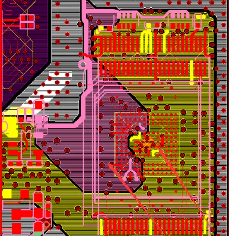
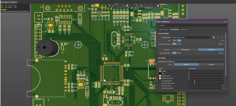
Step 4: Design the PCB Layout
The layout phase is critical for video PCB design. Follow these tips:
- Place Components Strategically: Group related components (e.g., video processor and connectors) close together to minimize trace lengths.
- Route High-Speed Traces: Keep video signal traces straight and avoid sharp bends. Use differential pair routing for signals like HDMI.
- Use Ground Planes: A solid ground plane under high-speed traces reduces noise and EMI.
- Add Decoupling Capacitors: Place them near power pins to filter noise.
For impedance control, calculate trace widths based on your board’s dielectric constant (typically 4.2 for FR-4 material) and stack-up. Online calculators can help with this.
Step 5: Verify and Test
Before manufacturing, run design rule checks (DRC) in your software to catch errors like unconnected pins or spacing violations. Simulate signal integrity if possible, especially for high-speed traces. After manufacturing, test the board with a multimeter for continuity and use an oscilloscope to check signal quality.
Video PCB Design Guide for Beginners: Best Practices
As a beginner, following best practices can save you time and prevent costly mistakes. This video PCB design guide for beginners highlights key tips to ensure success.
1. Start Small
Don’t jump into complex designs right away. Begin with a simple project, like a video switcher or a basic capture card, to learn the ropes of signal routing and power management.
2. Use Reference Designs
Many component manufacturers provide reference designs for video processing chips. These are pre-tested layouts you can adapt, reducing the risk of errors.
3. Prioritize Signal Integrity
Always route high-speed video signals first, before power or low-speed lines. Maintain consistent trace spacing (at least 3x the trace width) to avoid crosstalk.
4. Test Iteratively
Build and test your design in stages. For example, verify power delivery before connecting video components. This makes troubleshooting easier.
Simple Video PCB Projects for Beginners
Hands-on practice is the best way to learn. Here are a few simple video PCB projects to help you apply what you’ve learned. These projects target beginners and focus on fundamental skills.
Project 1: Video Signal Switcher
Objective: Create a PCB that switches between two video inputs (e.g., composite video) and outputs to a single display.
Components Needed:
- Video multiplexer IC
- Composite video connectors (RCA jacks)
- Toggle switch for input selection
- Power supply (5V)
Steps:
- Design a schematic with the multiplexer connecting two inputs to one output.
- Lay out the PCB, keeping video traces short and away from power lines.
- Assemble and test by connecting two video sources and a monitor.
Learning Outcome: Understand basic video signal routing and component placement.
Project 2: USB Video Capture Board
Objective: Build a PCB to capture analog video (e.g., from a camcorder) and convert it to digital via USB.
Components Needed:
- Analog-to-digital video converter chip
- USB interface IC
- Composite video input connector
- Power regulator (5V to 3.3V)
Steps:
- Create a schematic linking the video input to the converter and USB output.
- Design the layout with a ground plane under high-speed USB traces.
- Test with a computer to ensure video capture works at 480p or higher.
Learning Outcome: Learn about mixed-signal design and USB integration.
Common Challenges in Video PCB Design and How to Overcome Them
Designing video processing PCBs comes with challenges, especially for beginners. Here are some common issues and solutions.
Challenge 1: Signal Loss
Issue: High-speed video signals degrade over long traces, causing poor video quality.
Solution: Keep traces as short as possible (under 2 inches for gigabit signals if feasible) and use impedance-matched routing. Add repeaters or buffers for longer distances.
Challenge 2: Noise and Interference
Issue: EMI from nearby traces or external sources distorts video output.
Solution: Use a four-layer board with dedicated ground and power planes. Shield sensitive areas with copper pours or enclosures.
Challenge 3: Overheating
Issue: Video processing chips generate heat, risking component failure.
Solution: Add thermal vias under high-power components and ensure adequate airflow in the final enclosure.
Tools and Resources for Video PCB Design
To succeed in video PCB design, you’ll need the right tools and resources. Here are some recommendations for beginners.
Design Software
Use free or affordable PCB design tools that support schematic capture and layout. Look for software with built-in libraries for video components and simulation features for signal integrity analysis.
Learning Resources
Explore online tutorials, forums, and datasheets to deepen your knowledge. Manufacturer websites often provide application notes for video processing components, offering practical design tips.
Conclusion: Start Your Video PCB Design Journey Today
Designing a video processing PCB may seem daunting at first, but with the right approach, it’s an achievable skill for beginners. By mastering video PCB basics, following the video PCB design steps, and practicing with simple video PCB projects, you’ll build the confidence to tackle more complex designs. Remember to prioritize signal integrity, noise reduction, and power management in every project.
At ALLPCB, we’re here to support your journey with high-quality manufacturing services tailored to your needs. Whether you’re prototyping a basic video switcher or scaling up to a professional-grade board, start small, test often, and keep learning. Your first successful video PCB design is just a few steps away!


