In the fast-evolving world of electronics, managing heat is a critical challenge. Insulated Metal Substrate PCBs (IMS PCBs) offer a powerful solution for thermal management, ensuring devices run efficiently and reliably. If you're searching for insights on IMS PCB thermal conductivity, metal core PCB heat dissipation, MCPCB thermal resistance, insulated metal substrate thermal design, or PCB thermal management, you've come to the right place. This blog will explore how IMS PCBs work, why they excel in heat dissipation, and how they can elevate your electronic designs.
At ALLPCB, we understand the importance of thermal performance in modern electronics. Whether you're designing high-power LED systems or automotive circuits, this guide will provide actionable information to help you make informed decisions about using IMS PCBs for superior heat management.
What Are Insulated Metal Substrate PCBs (IMS PCBs)?
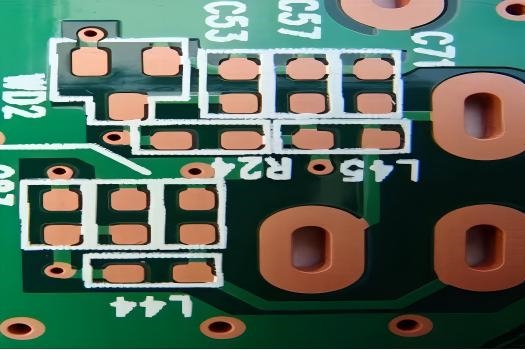
IMS PCBs, also known as Metal Core PCBs (MCPCBs), are specialized printed circuit boards designed to handle high heat levels. Unlike traditional PCBs made with FR-4 material, IMS PCBs feature a metal base layer—typically aluminum or copper—paired with a thin, thermally conductive dielectric layer and a copper circuit layer on top. This unique structure allows them to dissipate heat much more effectively than standard boards.
The primary purpose of an IMS PCB is to transfer heat away from critical components, preventing overheating and ensuring long-term reliability. With thermal conductivity values often ranging from 1 to 8 W/m·K (depending on the dielectric material), these boards outperform FR-4, which typically offers only about 0.3 W/m·K. This makes IMS PCBs ideal for applications where heat dissipation is a priority.
Why Thermal Management Matters in PCB Design
Heat is the enemy of electronic performance. Excessive temperatures can degrade components, reduce lifespan, and even cause system failures. For instance, in high-power applications like LED lighting, every 10°C rise in temperature can reduce the lifespan of an LED by up to 50%. Effective PCB thermal management is essential to keep operating temperatures within safe limits, typically below 85°C for most components.
Traditional PCBs struggle to handle high heat loads because their materials have low thermal conductivity. This is where IMS PCBs shine. By using a metal core, they provide a direct path for heat to escape, reducing thermal resistance and maintaining stable performance even under demanding conditions.
Key Benefits of IMS PCBs for Thermal Performance
IMS PCBs are a game-changer for engineers looking to optimize heat dissipation. Here are some of the standout advantages they offer:
- High Thermal Conductivity: With a metal base like aluminum (thermal conductivity of around 200 W/m·K) or copper (around 400 W/m·K), IMS PCBs efficiently transfer heat away from components. Even with the dielectric layer, overall thermal conductivity remains far superior to standard materials.
- Low Thermal Resistance: MCPCB thermal resistance is significantly lower than that of FR-4 boards. This means less heat buildup and better performance for high-power devices.
- Durability Under Stress: The metal core adds mechanical strength, making IMS PCBs resistant to vibration and thermal expansion, which is crucial in automotive or industrial applications.
- Lightweight Options: Aluminum-based IMS PCBs are lighter than copper alternatives, reducing the overall weight of the device without sacrificing thermal performance.
How IMS PCBs Enhance Metal Core PCB Heat Dissipation
The secret to metal core PCB heat dissipation lies in the design of IMS PCBs. The metal base acts as a heat sink, drawing heat away from hot components and spreading it across a larger surface area. This process minimizes hotspots and ensures even temperature distribution.
For example, in a high-power LED application, the heat generated by the LED (often exceeding 100°C at the junction) is quickly transferred through the dielectric layer to the metal core. From there, it can be dissipated into the surrounding environment or to an external heat sink. Studies show that IMS PCBs can reduce junction temperatures by 20-30°C compared to standard PCBs under similar conditions, significantly improving component reliability.
The dielectric layer, while less conductive than the metal base, is engineered to balance electrical insulation with thermal performance. Modern dielectric materials can achieve thermal conductivities of up to 3-8 W/m·K, ensuring minimal resistance to heat flow while preventing short circuits.
Understanding MCPCB Thermal Resistance
Thermal resistance measures how much a material opposes the flow of heat, typically expressed in °C/W (degrees Celsius per watt). A lower thermal resistance means better heat dissipation. In MCPCBs, thermal resistance is influenced by the thickness and quality of the dielectric layer, as well as the type of metal core used.
For instance, a typical IMS PCB with a 0.1 mm dielectric layer and an aluminum core might have a thermal resistance of around 0.5-1.0 °C/W. In contrast, a standard FR-4 board could have a thermal resistance of 20-30 °C/W or higher under similar conditions. This stark difference highlights why MCPCBs are the go-to choice for heat-sensitive applications.
Engineers can further reduce thermal resistance by optimizing the board design, such as minimizing dielectric thickness or using copper instead of aluminum for the core. However, these choices often involve trade-offs in cost and weight, which must be carefully considered during the design phase.
Insulated Metal Substrate Thermal Design: Best Practices
Designing an IMS PCB for optimal thermal performance requires careful planning. Here are some best practices to guide you through insulated metal substrate thermal design:
- Choose the Right Metal Core: Aluminum is cost-effective and lightweight, making it suitable for most applications. Copper offers superior thermal conductivity but is heavier and more expensive, ideal for extreme heat loads.
- Optimize Dielectric Thickness: A thinner dielectric layer reduces thermal resistance but may compromise electrical insulation. Aim for a balance based on your voltage requirements—common thicknesses range from 0.075 mm to 0.15 mm.
- Maximize Heat Spreading: Place high-power components strategically to allow heat to spread evenly across the metal core. Avoid clustering heat sources in one area.
- Incorporate Heat Sinks: Attach external heat sinks or cooling solutions to the metal core for enhanced dissipation in high-heat scenarios.
- Use Thermal Vias: While IMS PCBs rely less on vias for heat transfer due to the metal core, adding thermal vias near hot components can still improve performance.
Applications of IMS PCBs in PCB Thermal Management
IMS PCBs are widely used in industries where heat management is critical. Here are some common applications where they excel in PCB thermal management:
- LED Lighting: High-power LEDs generate significant heat, often requiring IMS PCBs to maintain safe operating temperatures and extend lifespan. These boards can handle power densities of up to 10 W/cm2 or more.
- Automotive Electronics: From engine control units to electric vehicle battery systems, IMS PCBs withstand harsh environments and high temperatures, often exceeding 125°C.
- Power Supplies: Switch-mode power supplies and converters rely on IMS PCBs to manage heat from high-current components, ensuring efficiency and reliability.
- Industrial Equipment: Heavy machinery and motor drives use IMS PCBs to handle thermal stress from continuous operation under heavy loads.
By leveraging the superior heat dissipation of IMS PCBs, engineers can push the boundaries of performance in these demanding fields.
Comparing IMS PCBs to Traditional PCBs for Thermal Performance
When it comes to thermal management, IMS PCBs clearly outperform traditional FR-4 boards. Let's break down the differences:
| Feature | IMS PCB | Traditional FR-4 PCB |
|---|---|---|
| Thermal Conductivity (W/m·K) | 1-8 (dielectric), 200-400 (metal core) | 0.3-0.5 |
| Thermal Resistance (°C/W) | 0.5-1.0 | 20-30 |
| Heat Dissipation Capability | Excellent (direct heat path via metal core) | Poor (relies on vias and external cooling) |
| Cost | Higher due to materials and manufacturing | Lower, widely available |
This comparison shows that while IMS PCBs come at a higher cost, their thermal performance makes them indispensable for high-heat applications. For low-power designs, traditional PCBs may still suffice, but as power demands increase, the switch to IMS becomes a necessity.
Challenges and Limitations of IMS PCBs
While IMS PCBs offer impressive benefits, they are not without challenges. Understanding these limitations can help engineers make informed decisions:
- Higher Cost: The use of metal cores and specialized dielectric materials increases manufacturing costs compared to standard PCBs. This can be a barrier for budget-conscious projects.
- Design Complexity: Working with metal cores requires specialized design software and manufacturing processes, which may add complexity to the development cycle.
- Limited Layer Count: IMS PCBs are typically single-sided or double-sided due to the metal core, making them less suitable for complex, multi-layer designs.
- Weight Considerations: While aluminum cores are lightweight, copper cores can add significant weight, which may be a concern in portable devices.
Despite these challenges, the thermal advantages of IMS PCBs often outweigh the drawbacks, especially in applications where heat management is non-negotiable.
How ALLPCB Supports Your IMS PCB Needs
At ALLPCB, we specialize in providing high-quality IMS PCBs tailored to your thermal management requirements. Our advanced manufacturing capabilities ensure precise control over dielectric thickness, metal core selection, and overall board design to maximize heat dissipation. Whether you're working on LED lighting, automotive systems, or industrial electronics, we offer customized solutions to meet your needs.
Our team of experts is ready to assist with every step of the process, from design consultation to final production. With fast prototyping and reliable delivery, we help you bring your projects to life without delays.
Conclusion: Elevate Your Designs with IMS PCBs
Insulated Metal Substrate PCBs are a cornerstone of modern PCB thermal management, offering unmatched thermal conductivity and heat dissipation for high-power applications. By understanding IMS PCB thermal conductivity, metal core PCB heat dissipation, MCPCB thermal resistance, and insulated metal substrate thermal design, you can unlock new levels of performance and reliability in your electronic designs.
From LED lighting to automotive electronics, IMS PCBs provide the thermal stability needed to push the limits of innovation. At ALLPCB, we're committed to helping you harness the power of these advanced boards with tailored solutions and expert support. Take the next step in optimizing your designs by exploring the possibilities of IMS PCBs today.
 ALLPCB


