 ALLPCB


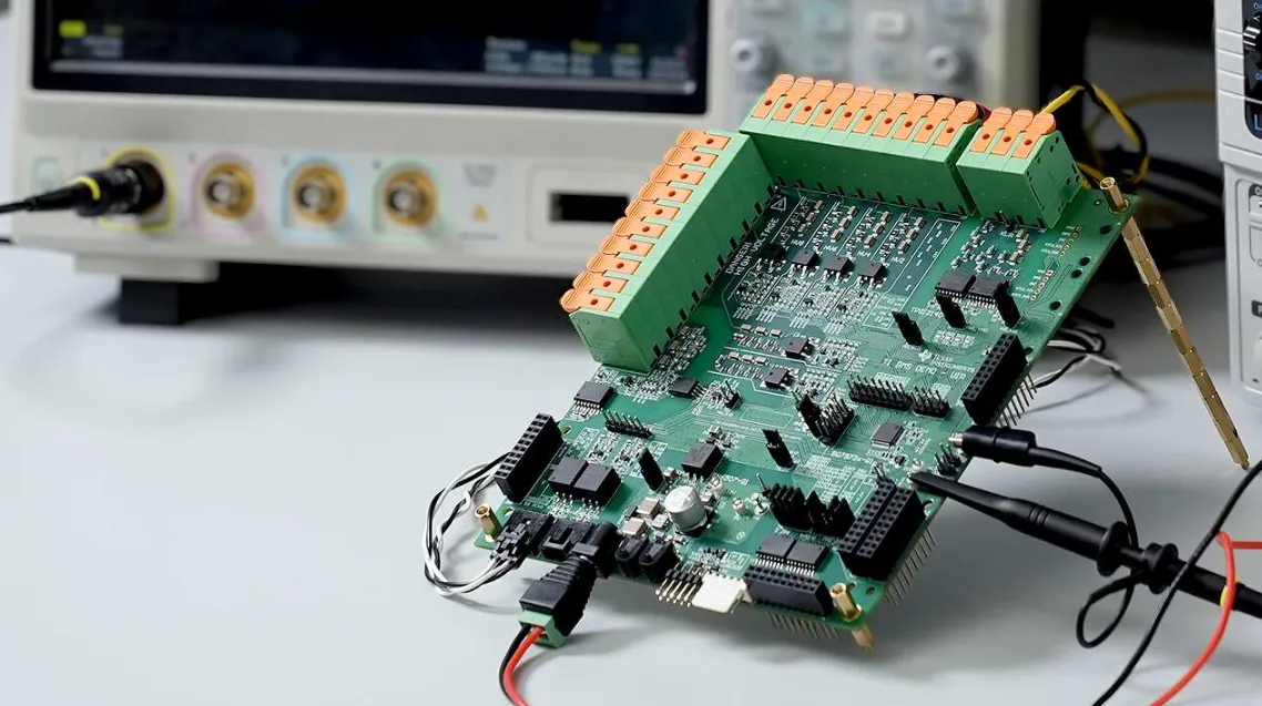
In the fast-evolving world of electric vehicles (EVs), battery management systems (BMS) play a critical role in ensuring safety, efficiency, and longevity. These systems often operate in high-temperature environments, making the choice of PCB materials essential for reliable performance. If you're looking for the best PCB materials for high-temperature EV battery management applications, the answer lies in selecting options with high Tg (glass transition temperature), excellent thermal conductivity, and resistance to issues like delamination and thermal stress. Materials such as high Tg FR-4, polyimide, and metal core PCBs are often ideal choices due to their ability to withstand extreme conditions.
In this comprehensive guide, we'll dive deeper into the properties of these materials, explore their benefits and challenges, and explain why they are suited for EV BMS applications. Whether you're an engineer designing cutting-edge systems or a manufacturer seeking durable solutions, this blog will provide actionable insights to help you make informed decisions.
Why PCB Material Selection Matters for EV Battery Management
EV battery management systems monitor and control critical parameters like voltage, current, and temperature to prevent overheating, overcharging, or short circuits. These systems often face temperatures exceeding 100°C, especially in high-power applications or fast-charging scenarios. Standard PCB materials may fail under such conditions, leading to performance issues or even catastrophic failures. Choosing the right material ensures thermal stability, mechanical strength, and long-term reliability.
Key factors to consider include thermal conductivity, coefficient of thermal expansion (CTE), resistance to delamination, and compatibility with lead-free soldering processes. Let’s explore the most suitable materials and how they address these challenges.
High Tg FR-4: A Reliable Choice for Moderate High-Temperature Needs
FR-4 is one of the most commonly used PCB materials, known for its balance of cost, performance, and availability. Standard FR-4 has a glass transition temperature (Tg) of around 130°C to 140°C, which is often insufficient for high-temperature EV applications. However, high Tg FR-4 variants, with Tg values ranging from 150°C to 180°C, offer improved thermal stability, making them suitable for moderate high-temperature environments.
High Tg FR-4 resists deformation and maintains structural integrity at elevated temperatures. It also provides a decent thermal conductivity of approximately 0.3 to 0.4 W/m·K, which helps dissipate heat to some extent. However, in extreme conditions above 150°C, it may still face risks of delamination—where layers of the PCB separate due to thermal stress. For EV BMS applications with temperatures consistently below this threshold, high Tg FR-4 can be a cost-effective solution.
Pros:
- Affordable compared to advanced materials
- Good mechanical strength and electrical insulation
- Compatible with lead-free soldering processes, which typically require reflow temperatures of 260°C or higher
Cons:
- Limited thermal conductivity for high-power applications
- Higher risk of thermal stress and delamination at extreme temperatures
For engineers working on EV systems with moderate thermal demands, high Tg FR-4 provides a practical starting point before moving to more advanced materials.
Polyimide: The Go-To Material for Extreme Heat Resistance
When temperatures in EV battery management systems exceed the limits of high Tg FR-4, polyimide emerges as a top choice. Polyimide PCBs are known for their exceptional thermal stability, with Tg values often exceeding 250°C. This makes them ideal for applications where temperatures can spike due to rapid charging or high current loads.
Polyimide also offers a low coefficient of thermal expansion (CTE), typically in the range of 12-20 ppm/°C, compared to 50-70 ppm/°C for standard FR-4. A lower CTE means less expansion and contraction during temperature changes, reducing thermal stress on components and solder joints. This property is especially critical in lead-free soldering, where higher reflow temperatures can exacerbate stress on the board.
Additionally, polyimide resists delamination even under prolonged exposure to heat, ensuring long-term reliability in harsh EV environments. Its thermal conductivity, while still modest at around 0.2-0.5 W/m·K, can be enhanced with design techniques like thermal vias.
Pros:
- Exceptional heat resistance for extreme temperatures
- Low CTE reduces thermal stress
- High resistance to delamination and chemical degradation
Cons:
- Higher cost compared to FR-4
- Lower thermal conductivity requires additional heat dissipation strategies
For EV BMS designs that prioritize durability in extreme heat, polyimide is often the material of choice, especially in compact or flex PCB configurations.
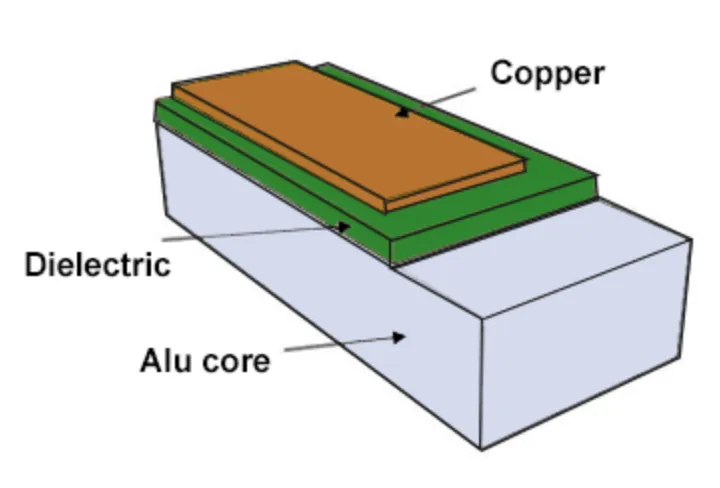
Metal Core PCB: Maximizing Thermal Conductivity for Heat Dissipation
In EV battery management systems, heat dissipation is often as critical as thermal resistance. Metal core PCBs (MCPCBs) address this by incorporating a metal base layer—usually aluminum or copper—with thermal conductivity values ranging from 1 to 4 W/m·K for aluminum and up to 400 W/m·K for copper. This is significantly higher than the thermal conductivity of FR-4 or polyimide, making MCPCBs ideal for high-power applications where heat must be quickly transferred away from sensitive components.
MCPCBs consist of a metal base, a dielectric layer for insulation, and a copper circuit layer. The metal core acts as a heat sink, spreading heat evenly across the board and reducing hotspots that could damage components or cause thermal stress. This design is particularly beneficial in EV BMS setups where power electronics generate substantial heat.
However, MCPCBs have a higher CTE (around 23 ppm/°C for aluminum) compared to polyimide, which can lead to thermal stress if not carefully managed. They are also heavier and more expensive than traditional materials, which may impact design considerations.
Pros:
- Superior thermal conductivity for effective heat dissipation
- Reduces hotspots and improves component lifespan
- Suitable for high-power EV applications
Cons:
- Higher CTE can cause thermal stress
- Increased weight and cost
For EV systems requiring robust thermal management, metal core PCBs provide an effective solution to keep temperatures under control.
Key Properties to Evaluate in High-Temperature PCB Materials
Selecting the right PCB material for EV battery management involves understanding several critical properties. Here’s a closer look at the factors that influence performance in high-temperature environments:
Thermal Conductivity
Thermal conductivity determines how effectively a material can transfer heat away from components. For high-power EV applications, materials with higher thermal conductivity, like metal core PCBs, are essential to prevent overheating. Values range widely—FR-4 at 0.3-0.4 W/m·K, polyimide at 0.2-0.5 W/m·K, and metal cores at 1-400 W/m·K depending on the metal used.
Coefficient of Thermal Expansion (CTE)
CTE measures how much a material expands or contracts with temperature changes. Mismatched CTE between the PCB and components can lead to thermal stress, cracking solder joints, or delamination. Polyimide’s low CTE (12-20 ppm/°C) makes it a safer bet for extreme temperature swings compared to FR-4 (50-70 ppm/°C) or aluminum-based MCPCBs (23 ppm/°C).
Delamination Resistance
Delamination occurs when layers of the PCB separate under thermal or mechanical stress. High-temperature environments exacerbate this risk, especially with materials like standard FR-4. Polyimide and high Tg FR-4 offer better resistance, ensuring the board remains intact over time.
Thermal Stress and Lead-Free Soldering Compatibility
Lead-free soldering, required by environmental regulations like RoHS, involves higher reflow temperatures (up to 260°C) compared to traditional lead-based soldering (around 220°C). This increases thermal stress on the PCB. Materials with high Tg and low CTE, such as polyimide, are better equipped to handle these conditions without warping or cracking.
Challenges in High-Temperature EV Battery Management Applications
Designing PCBs for EV BMS involves navigating several challenges beyond just material selection. High temperatures can degrade components, weaken solder joints, and cause board failures. Rapid temperature cycling—common during charging and discharging—adds further stress, increasing the risk of cracks or delamination.
Another challenge is balancing thermal performance with cost. While polyimide and metal core PCBs offer superior heat resistance and dissipation, their higher price points may not be feasible for all projects. Engineers often need to weigh these trade-offs and incorporate additional design features, such as thermal vias or heat sinks, to enhance performance.
Compatibility with lead-free soldering also remains a concern. The elevated temperatures required can push materials beyond their limits, especially if the Tg is too low. Selecting a material with a Tg at least 20-30°C above the soldering temperature is a good rule of thumb to minimize risks.
Best Practices for Designing High-Temperature PCBs for EV BMS
To maximize the performance of PCB materials in high-temperature EV applications, consider the following design tips:
- Match CTE Values: Choose materials with CTE values close to those of mounted components to reduce thermal stress on solder joints.
- Incorporate Thermal Vias: Add thermal vias to improve heat transfer from hot components to the board’s surface or a heat sink, especially with materials like polyimide that have lower thermal conductivity.
- Use High Tg Materials: Opt for materials with a Tg well above the operating and soldering temperatures to prevent deformation or failure.
- Test Under Real Conditions: Simulate the thermal cycling and peak temperatures of your EV application during testing to identify potential weaknesses in the PCB design.
- Consider Hybrid Designs: Combine materials, such as using a metal core base with a polyimide top layer, to balance thermal conductivity and heat resistance.
By following these practices, you can enhance the reliability and lifespan of your PCB in demanding EV battery management systems.
Conclusion: Choosing the Right Material for Your EV BMS Needs
Selecting the right PCB material for high-temperature EV battery management applications is a critical step in ensuring system safety and performance. High Tg FR-4 offers a cost-effective solution for moderate heat levels, while polyimide excels in extreme temperatures with its low CTE and delamination resistance. Metal core PCBs stand out for their superior thermal conductivity, making them ideal for high-power setups where heat dissipation is a priority.
Understanding key properties like thermal conductivity, CTE, and compatibility with lead-free soldering helps in making an informed choice tailored to your specific requirements. By prioritizing materials that address thermal stress and other challenges, you can design robust PCBs that withstand the harsh conditions of EV battery management.
At ALLPCB, we’re committed to supporting engineers and manufacturers with high-quality materials and manufacturing solutions for cutting-edge applications. Whether you’re working with high Tg FR-4, polyimide, or metal core PCBs, we’re here to help you achieve reliable and efficient designs for the future of electric vehicles.


