 ALLPCB


If you're dealing with point-of-sale (POS) system failures, the printed circuit board (PCB) is often the culprit. Whether it's a malfunctioning terminal, inconsistent transactions, or complete system downtime, understanding how to troubleshoot POS PCB issues can save time and money. In this comprehensive guide, we'll dive into common problems like component failure in POS systems, signal integrity issues, and provide a detailed troubleshooting guide for POS PCBs to help you get your system back up and running.
At its core, troubleshooting a POS PCB involves identifying the root cause of the failure—whether it's a damaged component, poor soldering, or environmental factors—and applying targeted solutions. This blog will walk you through the most frequent issues encountered in POS PCB failure analysis and offer practical steps for debugging POS PCBs. Let’s get started with everything you need to know to resolve these challenges efficiently.
Understanding the Importance of POS PCBs
Point-of-sale systems are the backbone of retail and hospitality businesses, handling everything from transactions to inventory management. At the heart of these systems lies the PCB, a critical component that connects and controls various hardware elements like card readers, displays, and printers. When a POS PCB fails, it can disrupt operations, leading to lost sales and frustrated customers.
POS PCBs are designed to withstand heavy usage, but they’re not immune to wear and tear. Factors like power surges, heat, humidity, and physical damage can cause failures. By mastering POS PCB failure analysis, you can minimize downtime and ensure smooth business operations. Let’s explore the most common issues that plague these boards and how to address them.
Common Issues in POS PCB Failures
Before diving into solutions, it’s essential to understand the typical problems that lead to POS system malfunctions. Here are the most frequent issues encountered during POS PCB failure analysis, explained in detail for clarity.
1. Component Failure in POS Systems
Component failure is one of the leading causes of POS PCB issues. These systems rely on various electronic components like resistors, capacitors, and microcontrollers to function. Over time, components can degrade due to heat, voltage spikes, or manufacturing defects. For instance, a capacitor might fail after prolonged exposure to high temperatures, leading to erratic behavior in the POS terminal.
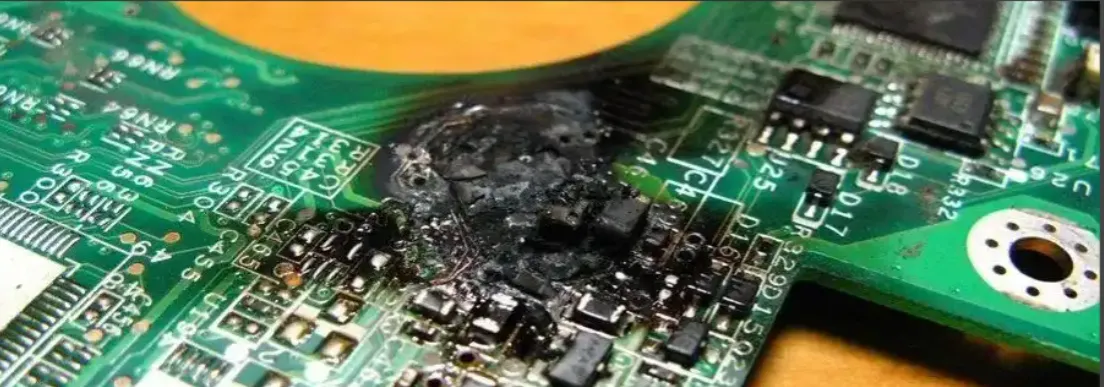
A common sign of component failure is intermittent functionality, such as a card reader that works sporadically or a display that flickers. In some cases, a burnt smell or visible damage on the PCB can indicate a failed component. Identifying the specific faulty part is the first step in debugging POS PCBs, and we’ll cover how to do this later in the troubleshooting guide for POS PCBs.
2. Signal Integrity Issues in POS Systems
Signal integrity refers to the quality of electrical signals as they travel through the PCB. In POS systems, where data transfer between components like card readers and processors must be fast and accurate, signal integrity issues can cause major problems. Common causes include electromagnetic interference (EMI), poor PCB layout design, or damaged traces.
For example, if the impedance of a trace is not properly matched—say, deviating from the standard 50 ohms for high-speed signals—it can lead to signal reflections and data loss. This might manifest as failed transactions or slow response times in the POS terminal. Addressing signal integrity issues often requires a combination of design optimization and hardware inspection, which we’ll discuss in the solutions section.
3. Power Supply Problems
POS systems are sensitive to power fluctuations. A sudden voltage spike or drop can damage the PCB or cause it to malfunction. Power supply issues often result from faulty adapters, unstable electrical grids, or internal regulator failures on the board. Symptoms include random reboots, system freezes, or complete failure to power on.
In one reported case, a retail chain experienced frequent POS downtime due to power surges during peak hours. Testing revealed that the input voltage exceeded the PCB’s tolerance of 12V by nearly 20%, frying critical components. Proper power management is crucial for preventing such failures.
4. Environmental Damage and Wear
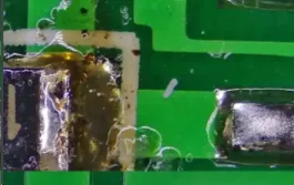
POS systems are often used in challenging environments—think greasy kitchens or dusty retail counters. Exposure to moisture, dust, or extreme temperatures can corrode PCB traces or damage components. Over time, this environmental wear can lead to short circuits or complete board failure.
For instance, a PCB exposed to humidity levels above 85% for extended periods may develop corrosion on solder joints, disrupting connectivity. Regular maintenance and protective measures can help mitigate these risks, as we’ll explore later.
Troubleshooting Guide for POS PCBs
Now that we’ve covered the common issues, let’s dive into a step-by-step troubleshooting guide for POS PCBs. This process will help you systematically identify and resolve problems, ensuring minimal disruption to your business.
Step 1: Visual Inspection
Start with a thorough visual check of the PCB. Look for obvious signs of damage, such as burnt components, cracked traces, or bulging capacitors. Use a magnifying glass if needed to spot tiny cracks or corrosion. Pay close attention to solder joints, as poor soldering is a frequent cause of failure.
Tip: If you notice a burnt component, note its location and markings (e.g., a resistor labeled “R1”). This will help in sourcing a replacement. A visual inspection can often reveal up to 30% of PCB issues without the need for advanced tools.
Step 2: Power Supply Testing
Use a multimeter to test the input voltage and ensure it matches the PCB’s specifications, typically between 5V and 12V for most POS systems. Check for continuity in power traces to confirm there are no breaks. If the voltage is outside the acceptable range (e.g., above 13V for a 12V system), the power supply or regulator may need replacement.
Additionally, inspect for ripple voltage using an oscilloscope. Excessive ripple—say, above 100mV—can indicate a failing capacitor in the power circuit, which can lead to unstable operation.
Step 3: Component Testing for Failure in POS Systems
Once power issues are ruled out, test individual components for functionality. Use a multimeter to check resistors, capacitors, and diodes. For example, a capacitor should show a steady increase in resistance when tested; if it reads as a short circuit, it’s likely failed.
For more complex components like microcontrollers or integrated circuits, you may need a logic analyzer to verify their operation. If a component is faulty, desolder it carefully and replace it with an identical part, ensuring proper alignment and soldering techniques to avoid further damage.
Step 4: Debugging POS PCBs for Signal Integrity Issues
Signal integrity issues require a deeper level of debugging. Use an oscilloscope to measure signal quality on critical traces, such as those connecting the card reader to the processor. Look for noise, overshoot, or undershoot in the waveform. For high-speed signals, ensure the rise time is within acceptable limits—typically under 1 nanosecond for modern POS systems.
If interference is detected, check for nearby sources of EMI, such as unshielded cables or motors. Rerouting traces or adding shielding can help. In cases of poor PCB design, consider consulting with a professional for a layout revision to match impedance values, often targeting 50 ohms for data lines.
Step 5: Environmental and Mechanical Checks
Inspect the POS system’s environment for factors like high humidity or dust buildup. Use a compressed air can to clean the PCB, and consider applying a conformal coating to protect against moisture if the system operates in harsh conditions. Also, check for loose connections or physical damage caused by vibrations or drops, as these can crack solder joints or traces.
Solutions and Preventative Measures for POS PCB Failures
Once you’ve identified the issue using the troubleshooting guide for POS PCBs, it’s time to apply solutions and take steps to prevent future failures. Here are actionable fixes for the common problems discussed earlier.
Solution 1: Replacing Failed Components
For component failure in POS systems, replace damaged parts with high-quality alternatives. Ensure the replacement matches the original specifications—e.g., a capacitor with the same capacitance (like 10μF) and voltage rating (like 16V). Use proper soldering tools to avoid damaging nearby components during replacement.
Solution 2: Improving Signal Integrity
To resolve signal integrity issues, optimize the PCB layout by minimizing trace lengths and avoiding sharp bends. Add ground planes to reduce EMI, and use termination resistors if signal reflections are a problem. For existing boards, external shielding or ferrite beads can help filter out noise.
Solution 3: Stabilizing Power Supply
Install surge protectors or uninterruptible power supplies (UPS) to protect against voltage spikes. Regularly test the power adapter to ensure it delivers a stable output, ideally within ±5% of the rated voltage (e.g., 11.4V to 12.6V for a 12V system). Replace faulty regulators on the PCB if internal power management is the issue.
Solution 4: Protecting Against Environmental Damage
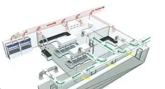
Place POS systems in well-ventilated areas to avoid overheating, and use enclosures to shield against dust and moisture. If humidity is a concern, silica gel packs near the PCB can absorb excess moisture. For high-risk environments, apply a conformal coating to the board for added protection.
Advanced Tips for Debugging POS PCBs
For engineers or technicians with advanced skills, consider using thermal imaging cameras to detect hot spots on the PCB, which can indicate failing components or poor design. Additionally, firmware updates can sometimes resolve issues caused by software-hardware mismatches, so check for updates from the POS system manufacturer.
Investing in simulation software to model signal integrity before manufacturing new boards can also prevent future issues. These tools can predict impedance mismatches or EMI problems, allowing for design adjustments early on.
Conclusion: Mastering POS PCB Failure Analysis
Troubleshooting POS PCB failures doesn’t have to be a daunting task. By following this detailed guide, you can tackle common issues like component failure in POS systems, signal integrity issues, and environmental damage with confidence. Whether you’re conducting a visual inspection, testing power supply stability, or debugging POS PCBs with an oscilloscope, a systematic approach is key to quick and effective solutions.
Preventative measures, such as stabilizing power input and protecting against harsh environments, can significantly extend the lifespan of your POS PCBs. With the right tools and knowledge, you can minimize downtime and keep your business running smoothly. Remember, consistent maintenance and early detection are your best allies in avoiding costly repairs down the line.
By mastering POS PCB failure analysis and applying the tips in this troubleshooting guide for POS PCBs, you’re well-equipped to handle any challenge that comes your way. Keep this resource handy for the next time your system encounters an issue, and you’ll be back to business in no time.


