 ALLPCB


Solar Printed Circuit Boards (PCBs) are the backbone of solar energy systems, managing power distribution and ensuring efficient operation. However, failures in these critical components can lead to system downtime and reduced energy output. If you're an engineer looking for actionable solutions to common issues like open circuit solar PCB, short circuit solar PCB, component failure solar PCB, and environmental damage solar PCB, this guide is for you. We'll dive deep into solar PCB failure analysis, offering practical troubleshooting steps to help you identify and resolve problems quickly.
In this comprehensive blog, we’ll break down the most frequent solar PCB failures, their causes, and step-by-step troubleshooting methods. Whether you're maintaining a residential solar setup or a large-scale solar farm, these insights will help you keep systems running smoothly.
Why Solar PCB Failures Matter
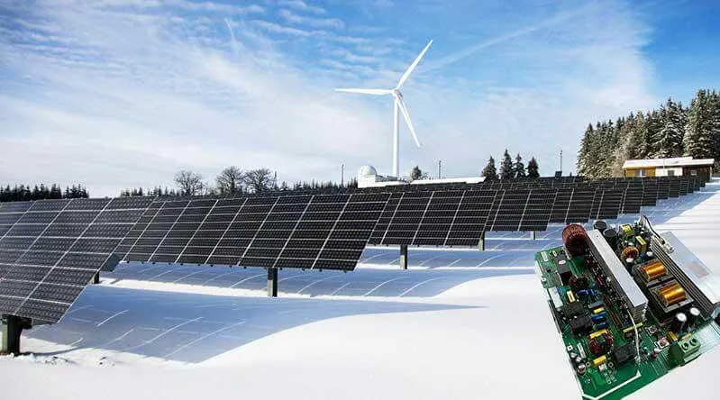
Solar PCBs are exposed to harsh conditions, from extreme temperatures to moisture and dust. These factors, combined with design or manufacturing flaws, can lead to failures that disrupt energy production. Understanding solar PCB failure analysis is essential for engineers to minimize downtime, reduce repair costs, and extend the lifespan of solar systems. A single failure in a solar array can drop efficiency by up to 20%, according to industry studies, making quick diagnosis and repair a priority.
Common Types of Solar PCB Failures
Before diving into troubleshooting, let’s explore the most common solar PCB failures engineers encounter. By identifying the type of issue, you can narrow down the root cause and apply the right fix.
1. Open Circuit Solar PCB Failures
An open circuit in a solar PCB occurs when there's a break in the conductive path, preventing current from flowing. This can result from cracked traces, poor soldering, or physical damage. When an open circuit happens, the affected section of the solar system may stop producing power entirely.
Causes:
- Mechanical stress causing trace cracks (e.g., during installation or thermal expansion).
- Corrosion of copper traces due to moisture exposure.
- Manufacturing defects like incomplete soldering joints.
Impact: Open circuits can reduce system output by isolating panels or components. For example, a single open circuit in a string of panels can cut power output by 50% or more in that string.
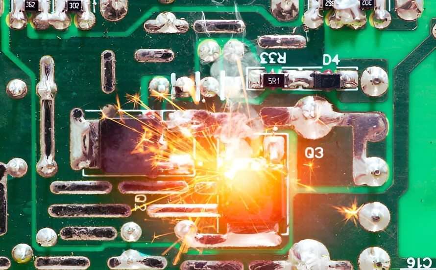
2. Short Circuit Solar PCB Failures
A short circuit solar PCB failure happens when two conductive paths come into unintended contact, causing current to bypass the intended route. This can lead to overheating, component burnout, or even fires in severe cases.
Causes:
- Insulation breakdown between traces due to moisture or dust buildup.
- Physical damage, such as a screw piercing the PCB during assembly.
- Solder bridges formed during manufacturing.
Impact: Short circuits can cause localized heating, with temperatures exceeding 150°C, leading to permanent damage or safety hazards.
3. Component Failure Solar PCB Issues
Component failure on a solar PCB refers to the malfunction of individual parts like diodes, capacitors, or transistors. These components are critical for regulating voltage and current in solar systems.
Causes:
- Overvoltage or overcurrent conditions, often from power surges (e.g., lightning strikes).
- Thermal stress degrading components over time, especially in hot climates where temperatures exceed 85°C.
- Poor quality or counterfeit components failing prematurely.
Impact: A failed bypass diode, for instance, can lead to hot spots on solar panels, reducing efficiency by up to 30% in affected areas.
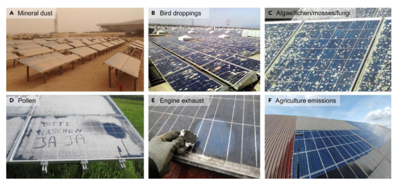
4. Environmental Damage Solar PCB Failures
Environmental factors are a leading cause of solar PCB failures. Since solar systems are often outdoors, PCBs face constant exposure to weather-related stressors.
Causes:
- Moisture ingress causing corrosion of traces and solder joints (common in humid regions with over 80% relative humidity).
- UV radiation degrading PCB materials over time.
- Dust and debris accumulation leading to insulation breakdown or overheating.
Impact: Environmental damage can shorten PCB lifespan by 5-10 years if not addressed through proper design or maintenance.
Step-by-Step Troubleshooting Guide for Solar PCB Failures
Now that we’ve covered the common failures, let’s walk through a practical troubleshooting process for solar PCB failure analysis. Follow these steps to systematically diagnose and resolve issues.
Step 1: Visual Inspection
Start with a thorough visual check of the solar PCB. Look for obvious signs of damage such as:
- Cracked or broken traces (indicative of open circuit solar PCB issues).
- Burn marks or discoloration (common in short circuit solar PCB failures).
- Swollen or leaking capacitors (a sign of component failure solar PCB problems).
- Corrosion or residue from moisture (linked to environmental damage solar PCB issues).
Use a magnifying glass or microscope for small-scale damage. Document any findings with photos for reference during repairs.
Step 2: Electrical Testing
Once visual issues are noted, perform electrical tests to confirm the type of failure. Use a multimeter or specialized PCB testing equipment for accurate readings.
- Continuity Test: Check for open circuits by measuring resistance across traces. A reading of infinite resistance indicates a break.
- Short Circuit Test: Measure resistance between adjacent traces or pads. A reading close to 0 ohms suggests a short.
- Component Testing: Test individual components like diodes and capacitors for proper operation. For example, a bypass diode should show a forward voltage drop of around 0.7V for silicon types.
Note: Always disconnect power before testing to avoid injury or further damage. Typical solar PCB voltages can range from 12V to 1000V in large systems.
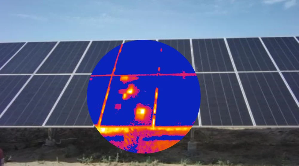
Step 3: Thermal Imaging
For issues not visible to the naked eye, use a thermal camera to detect hot spots. Excessive heat (above 100°C) often points to short circuits or failing components. This is especially useful for diagnosing short circuit solar PCB failures or component failure solar PCB issues under load.
Step 4: Environmental Assessment
Evaluate the installation environment for factors contributing to environmental damage solar PCB failures. Check for:
- Signs of water ingress in enclosures (look for IP ratings below IP65, which may not protect against moisture).
- Dust or debris buildup on or around the PCB.
- Exposure to direct sunlight without UV-resistant coatings.
Record environmental data like humidity (using a hygrometer) and temperature (using a thermometer) to correlate with failure patterns.
Step 5: Repair or Replace
Based on your findings, decide whether to repair or replace the affected PCB or components:
- For open circuit solar PCB issues, re-solder broken traces or replace damaged sections if possible.
- For short circuit solar PCB failures, remove solder bridges or insulate exposed areas with conformal coating.
- For component failure solar PCB problems, replace defective parts with high-quality alternatives rated for solar applications (e.g., capacitors with 105°C temperature ratings).
- For severe environmental damage solar PCB issues, consider replacing the board and upgrading enclosure protection to prevent recurrence.
Preventing Solar PCB Failures: Best Practices
While troubleshooting is essential, prevention is even better. Here are practical tips to minimize solar PCB failures and extend system reliability.
1. Use High-Quality Materials
Choose PCBs and components designed for solar applications. Opt for boards with FR-4 material or higher, rated for temperatures up to 125°C, and components with proven durability in harsh conditions.
2. Apply Protective Coatings
Use conformal coatings to shield PCBs from moisture, dust, and UV radiation. Silicone or acrylic coatings can reduce environmental damage solar PCB risks by up to 70%, based on industry testing.
3. Design for Thermal Management
Incorporate heat sinks or ventilation in solar PCB designs to manage temperatures. Overheating is a leading cause of component failure solar PCB issues, especially in regions with ambient temperatures above 40°C.
4. Regular Maintenance
Schedule routine inspections to catch early signs of wear or environmental damage. Clean PCBs with compressed air or isopropyl alcohol to remove dust and debris, preventing short circuit solar PCB failures.
5. Test Under Real Conditions
Before full deployment, test solar PCBs under simulated environmental stress (e.g., humidity chambers at 85% RH and temperature cycling from -20°C to 85°C). This helps identify potential weaknesses before they become field failures.
Tools and Equipment for Solar PCB Troubleshooting
Having the right tools can make solar PCB failure analysis faster and more accurate. Here’s a list of essentials for engineers:
- Multimeter: For measuring voltage, current, and resistance (look for models with accuracy of ±0.5%).
- Thermal Camera: To detect overheating (resolution of 160x120 pixels or better for detailed imaging).
- Soldering Kit: For repairing open circuits or replacing components (include a soldering iron with adjustable temperature up to 350°C).
- Magnifying Tools: For inspecting small-scale damage (a 10x magnifying glass or digital microscope).
- Environmental Sensors: To measure temperature and humidity at the installation site.
Conclusion: Mastering Solar PCB Failure Analysis
Solar PCB failures, whether due to open circuits, short circuits, component issues, or environmental damage, can significantly impact the performance of solar energy systems. By following the troubleshooting steps outlined in this guide, engineers can systematically diagnose and resolve these issues, ensuring minimal downtime and maximum efficiency. From visual inspections to electrical testing and preventive measures, a proactive approach to solar PCB failure analysis is key to maintaining reliable systems.
Implementing best practices like using high-quality materials, applying protective coatings, and conducting regular maintenance can prevent many common failures. With the right tools and knowledge, you can tackle challenges like open circuit solar PCB, short circuit solar PCB, component failure solar PCB, and environmental damage solar PCB head-on, keeping solar systems running at peak performance.


