ALLPCB


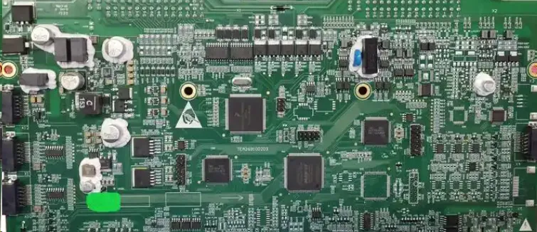
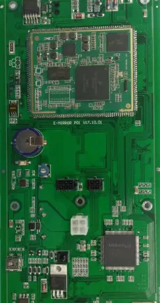
Advanced Driver Assistance Systems (ADAS) are transforming the automotive industry by enhancing safety and driving comfort. At the heart of these systems are Printed Circuit Boards (PCBs) that must operate flawlessly under harsh conditions. Ensuring ADAS PCB reliability is critical, and this blog dives deep into the testing and validation methods—like ADAS PCB testing, automotive PCB validation, environmental testing for PCBs, accelerated life testing, and functional testing of ADAS PCBs—that guarantee performance and durability. Whether you're an engineer or a manufacturer, this guide offers practical insights to help you build robust ADAS solutions.
Why ADAS PCB Reliability Matters
ADAS technologies, such as lane departure warnings, adaptive cruise control, and automatic emergency braking, rely on PCBs to process data from sensors, cameras, and radar systems in real time. A failure in these PCBs could lead to catastrophic consequences, making reliability non-negotiable. Harsh automotive environments, including extreme temperatures, vibrations, and humidity, further complicate the challenge. That’s why rigorous testing and validation are essential to ensure these boards withstand the toughest conditions while maintaining precision.
Key Challenges in ADAS PCB Design and Reliability
Before diving into testing methods, it’s important to understand the unique challenges ADAS PCBs face:
- High-Speed Signal Integrity: ADAS systems process data at high speeds, often requiring signal transmission rates above 1 Gbps for radar and camera inputs. Any signal loss or interference can disrupt functionality.
- Thermal Stress: Automotive environments can expose PCBs to temperature swings from -40°C to 85°C, risking thermal expansion and component failure.
- Vibration and Mechanical Stress: Constant vibrations from driving on rough terrain can cause solder joint cracks or component detachment.
- Electromagnetic Interference (EMI): With multiple electronic systems in a vehicle, EMI can interfere with ADAS PCB performance, leading to data errors.
Testing and validation methods are designed to address these challenges, ensuring that every board meets stringent automotive standards like ISO 26262 for functional safety.
Core Testing and Validation Methods for ADAS PCBs
Let’s explore the primary methods used to ensure ADAS PCB reliability, focusing on practical approaches and specific parameters.
1. Functional Testing of ADAS PCBs
Functional testing verifies that an ADAS PCB performs its intended tasks under real-world conditions. This method simulates the board’s operation within the vehicle’s system to check for correct data processing and response times.
- Process: Engineers connect the PCB to a test setup mimicking the ADAS environment, inputting signals from sensors (e.g., radar detecting an obstacle at 50 meters). They measure outputs like response latency, ensuring it’s below 100 milliseconds for critical functions like emergency braking.
- Tools: Automated test equipment (ATE) and custom software are used to replicate sensor inputs and monitor outputs.
- Benefit: Identifies logic errors or firmware issues before deployment, ensuring seamless integration with other vehicle systems.
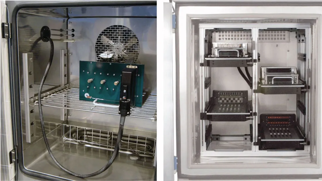
2. Environmental Testing for PCBs
Environmental testing subjects ADAS PCBs to the extreme conditions they’ll face in vehicles. This ensures they can handle temperature fluctuations, humidity, and other stressors without failing.
- Temperature Cycling: Boards are tested between -40°C and 85°C for 500 to 1000 cycles to simulate years of thermal stress. This checks for issues like delamination or solder joint cracks.
- Humidity Testing: PCBs are exposed to 85% relative humidity at 85°C for 96 hours to test for corrosion or insulation breakdown.
- Salt Spray Testing: Simulates exposure to road salt in winter conditions, ensuring no degradation of conductive traces or components after 48 hours.
- Benefit: Confirms the board’s durability in diverse climates, from freezing winters to humid tropics.
Standards like IPC-TM-650 provide guidelines for these tests, ensuring consistency across the industry.
3. Accelerated Life Testing (ALT)
Accelerated life testing pushes ADAS PCBs beyond normal operating conditions to predict long-term reliability in a shorter time frame. This method is vital for meeting automotive durability expectations of 10-15 years.
- Process: Boards undergo elevated stress levels, such as temperatures up to 125°C or vibration frequencies of 20-2000 Hz at 5g acceleration, for condensed periods (e.g., 100 hours representing 5 years of use).
- Data Analysis: Failure rates are analyzed using models like the Arrhenius equation to estimate lifespan under normal conditions.
- Benefit: Identifies weak points in design or materials early, reducing the risk of field failures.
4. Automotive PCB Validation for Signal Integrity and EMI
Automotive PCB validation focuses on electrical performance, especially for high-speed ADAS applications where signal integrity and EMI are major concerns.
- Signal Integrity Testing: Using oscilloscopes and network analyzers, engineers measure impedance (typically targeting 50 ohms for high-speed lines) and signal loss (aiming for less than 3 dB at 1 GHz). This ensures data from sensors reaches the processor without distortion.
- EMI Testing: Boards are tested in an anechoic chamber to detect unwanted emissions and susceptibility to external interference, adhering to standards like CISPR 25 for automotive electronics.
- Benefit: Guarantees reliable communication between ADAS components, preventing errors in critical safety functions.
5. Mechanical and Vibration Testing
Mechanical testing evaluates an ADAS PCB’s ability to withstand physical stress from vehicle motion. Vibration and shock are common causes of failure in automotive environments.
- Vibration Testing: Boards are subjected to random vibrations at 5-20g across 10-2000 Hz for 8 hours per axis, simulating rough road conditions.
- Shock Testing: Simulates sudden impacts (e.g., potholes) with forces up to 50g for 11 milliseconds, ensuring components remain intact.
- Benefit: Validates structural integrity, preventing issues like cracked solder joints or detached components during operation.
Industry Standards and Compliance for ADAS PCB Testing
Adhering to industry standards is a cornerstone of ADAS PCB reliability. These standards provide a framework for testing and validation, ensuring consistency and safety.
- ISO 26262: Focuses on functional safety for automotive electronics, requiring risk assessment and mitigation strategies during PCB design and testing.
- IPC-A-600 and IPC-A-610: Define acceptability criteria for PCB manufacturing and assembly, covering aspects like solder quality and component placement.
- AEC-Q100: A qualification standard for automotive electronic components, including stress tests for temperature, humidity, and electrical performance.
Compliance with these standards not only ensures reliability but also builds trust with automotive manufacturers and end users.
Best Practices for Effective ADAS PCB Testing
To maximize the effectiveness of testing and validation, consider these best practices:
- Design for Testability (DFT): Incorporate test points and accessible connectors during the design phase to simplify functional and electrical testing.
- Automate Where Possible: Use automated optical inspection (AOI) and in-circuit testing (ICT) to detect manufacturing defects early, reducing manual errors.
- Iterative Testing: Conduct tests at multiple stages—prototype, pre-production, and post-assembly—to catch issues before mass production.
- Simulate Real-World Scenarios: Tailor environmental and functional tests to match the specific vehicle application, such as off-road or urban driving conditions.
- Document Results: Maintain detailed records of test parameters, failures, and corrective actions to improve future designs.
Common Pitfalls to Avoid in ADAS PCB Testing
Even with robust testing methods, certain oversights can undermine reliability:
- Ignoring Edge Cases: Failing to test for rare but severe conditions, like extreme cold starts at -40°C with full system load, can lead to unexpected failures.
- Overlooking EMI: Not conducting thorough EMI testing can result in interference from other vehicle systems, disrupting ADAS functionality.
- Insufficient Sample Size: Testing only a few boards may miss batch-specific defects, so ensure a statistically significant sample size (e.g., 30-50 units per batch).
- Skipping Post-Assembly Testing: Assembly errors like cold solder joints can go undetected without final functional or environmental testing.
The Role of Collaboration in ADAS PCB Reliability
Achieving reliable ADAS PCBs is a team effort. Close collaboration between PCB designers, testing engineers, and automotive system integrators ensures that all requirements—from signal integrity to environmental durability—are met. Regular feedback loops during testing phases help refine designs and address potential issues early. Partnering with experienced manufacturing and testing providers can also streamline the process, leveraging their expertise in automotive standards and advanced testing equipment.
Future Trends in ADAS PCB Testing and Validation
As ADAS technology evolves, so do the methods for testing and validation. Emerging trends include:
- AI-Driven Testing: Machine learning algorithms are being used to predict failure modes and optimize test parameters, reducing testing time.
- Higher Integration Levels: With ADAS PCBs incorporating more functions (e.g., AI processing for autonomous driving), testing must adapt to handle increased complexity and power demands.
- Over-the-Air (OTA) Diagnostics: Future ADAS systems may include built-in diagnostics to monitor PCB health in real time, reducing reliance on periodic physical testing.
Staying ahead of these trends ensures that testing processes remain relevant and effective as automotive technology advances.
Conclusion: Building Trust Through Rigorous Testing
Ensuring ADAS PCB reliability is a complex but critical task. By employing a combination of functional testing of ADAS PCBs, environmental testing for PCBs, accelerated life testing, and automotive PCB validation, manufacturers can build boards that perform flawlessly in the harshest conditions. Adhering to industry standards and adopting best practices further enhances trust in these safety-critical systems. At ALLPCB, we’re committed to supporting engineers with high-quality manufacturing and testing solutions to meet the demanding needs of ADAS applications. With the right testing methods, you can drive innovation while prioritizing safety and reliability on the road.