 ALLPCB


In the fast-evolving world of automotive technology, Advanced Driver Assistance Systems (ADAS) are transforming how we drive, making vehicles safer and smarter. A key component behind the success of ADAS is the use of rigid-flex PCBs (Printed Circuit Boards). These hybrid boards combine the stability of rigid PCBs with the adaptability of flexible circuits, offering unique advantages for automotive applications. But what makes rigid-flex PCBs so vital for ADAS, and what challenges do engineers face in designing them? In this comprehensive guide, we’ll explore the benefits and challenges of rigid-flex PCB design for ADAS, focusing on automotive flexible PCB design, connecting multiple ADAS modules, dynamic bending in rigid-flex PCBs, and material selection for rigid-flex applications.
What Are Rigid-Flex PCBs and Why Are They Important for ADAS?
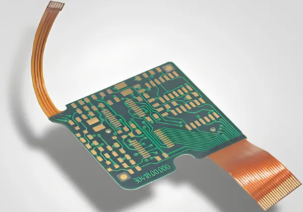
Rigid-flex PCBs are a blend of rigid and flexible circuit boards, integrated into a single unit. The rigid sections provide structural support for mounting components, while the flexible sections allow the board to bend and fit into tight or irregular spaces. In ADAS applications, where space is often limited and reliability is critical, rigid-flex PCBs are a game-changer. They enable compact designs for systems like adaptive cruise control, lane departure warnings, and parking assistance, ensuring seamless communication between sensors, cameras, and control units.
For engineers working on automotive flexible PCB design, rigid-flex technology addresses the need for durability and performance in harsh environments. Whether it’s connecting multiple ADAS modules or withstanding vibrations and temperature changes, these boards are built to handle the demands of modern vehicles. Let’s dive deeper into the specific benefits and challenges of using rigid-flex PCBs in ADAS.
Benefits of Rigid-Flex PCB Design for ADAS Applications
1. Space Efficiency and Compact Design
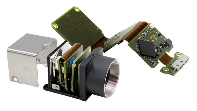
One of the standout advantages of rigid-flex PCBs in ADAS is their ability to save space. Modern vehicles are packed with electronics, and ADAS components like radar sensors, LiDAR, and cameras need to fit into tight areas. Rigid-flex PCBs can be folded or bent to conform to the vehicle’s design, reducing the overall footprint. For instance, a rigid-flex board can connect a front-facing camera to a central processing unit without requiring bulky connectors or additional wiring, cutting down on both space and weight.
2. Enhanced Reliability in Harsh Automotive Environments
Automotive systems must endure extreme conditions, from freezing winters to scorching summers, along with constant vibrations and shocks. Rigid-flex PCBs are designed to withstand these challenges. With fewer connectors and solder joints compared to traditional rigid boards, they minimize points of failure. This reliability is crucial for ADAS rigid-flex PCB applications, where a single malfunction in a collision avoidance system could have serious consequences.
3. Seamless Integration for Connecting Multiple ADAS Modules
ADAS relies on multiple components working together, such as sensors, cameras, and processing units. Rigid-flex PCBs excel at connecting multiple ADAS modules efficiently. The flexible sections of the board can span across different areas of a vehicle, linking disparate systems without the need for excessive cabling. This not only simplifies assembly but also reduces electromagnetic interference (EMI), which can disrupt high-speed data transmission. For example, a single rigid-flex PCB might connect a radar sensor on the bumper to a control unit in the dashboard, ensuring real-time data flow with minimal signal loss.
4. Support for Dynamic Bending in Rigid-Flex PCBs
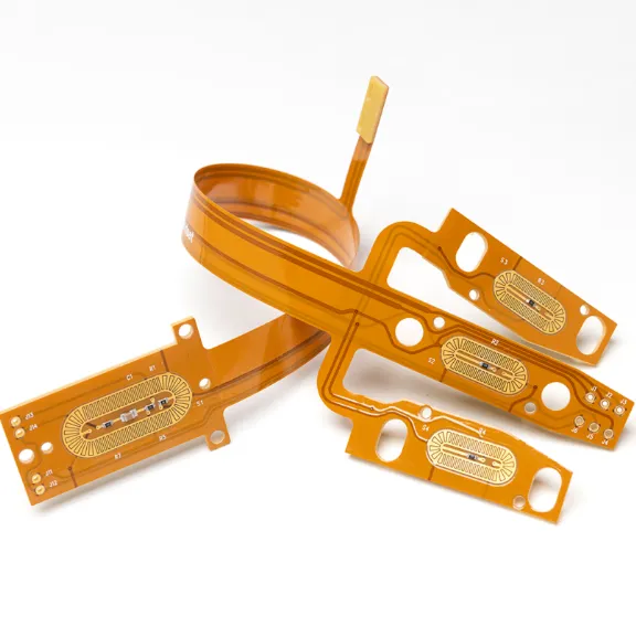
Dynamic bending in rigid-flex PCBs is a critical feature for automotive applications. Unlike static flex boards that are bent once during installation, dynamic flex boards can endure repeated bending over time. In ADAS, this is particularly useful for components mounted in areas prone to movement or vibration, such as adjustable camera systems or sensors on movable parts. Properly designed rigid-flex PCBs can handle bending radii as tight as 0.5 mm in dynamic applications, ensuring long-term performance without cracking or delamination.
5. Reduced Weight for Improved Fuel Efficiency
Weight reduction is a priority in automotive design, as it directly impacts fuel efficiency and electric vehicle range. Rigid-flex PCBs contribute to this goal by eliminating the need for heavy connectors and cables. A typical rigid-flex design can reduce the weight of an ADAS module by up to 20% compared to traditional rigid PCB assemblies, making it a preferred choice for manufacturers aiming to optimize vehicle performance.
Challenges in Rigid-Flex PCB Design for ADAS Applications
While the benefits of rigid-flex PCBs are clear, their design and implementation come with unique challenges. Engineers must navigate these hurdles to ensure the boards meet the stringent requirements of ADAS systems.
1. Complexity in Automotive Flexible PCB Design
Designing a rigid-flex PCB for automotive use is far more complex than designing a standard rigid board. The process involves balancing the rigid and flexible sections, determining the optimal layer stack-up, and ensuring signal integrity across bends. For ADAS applications, where high-frequency signals (often exceeding 1 GHz for radar systems) are common, maintaining impedance control is critical. A mismatch in impedance can lead to signal degradation, affecting the performance of safety-critical systems. Engineers often use simulation tools to model signal paths and test designs before production, adding time and cost to the development process.
2. Material Selection for Rigid-Flex Durability
Material selection for rigid-flex PCBs is a significant challenge, especially for ADAS applications. The flexible sections typically use polyimide films due to their high thermal stability and flexibility, while rigid sections often use FR-4 or similar materials for structural support. However, combining these materials requires careful consideration of their thermal expansion rates to prevent delamination under temperature fluctuations (ranging from -40°C to 85°C in automotive environments). Additionally, copper foil thickness must be chosen to balance flexibility and conductivity—thinner foils (e.g., 18 μm) enhance bending but may not support high current demands in power-intensive ADAS modules.
3. Managing Dynamic Bending Stress
While dynamic bending in rigid-flex PCBs offers flexibility, it also poses a risk of mechanical failure if not managed properly. Repeated bending can cause fatigue in the copper traces or dielectric layers, leading to cracks or breaks over time. For ADAS systems that require millions of bending cycles, engineers must design the flex areas with wider traces and larger bend radii to distribute stress evenly. Testing for dynamic bending often involves subjecting prototypes to accelerated life cycles, simulating years of use in a matter of weeks, to ensure reliability.
4. Cost Considerations in Production
Rigid-flex PCBs are more expensive to manufacture than traditional rigid boards due to their complex design and specialized materials. The cost can be a significant barrier, especially for high-volume automotive production where every penny counts. For instance, the additional steps required for laminating rigid and flexible layers can increase production costs by 30-50% compared to standard PCBs. Engineers must weigh these costs against the benefits of space savings and reliability when deciding whether to use rigid-flex designs in ADAS modules.
5. Signal Integrity and EMI Challenges
In ADAS rigid-flex PCB designs, maintaining signal integrity across flexible sections is a persistent challenge. High-speed signals, such as those used in LiDAR or camera systems, can experience loss or distortion when passing through bends. Additionally, the tight integration of multiple ADAS modules increases the risk of EMI, which can interfere with critical safety functions. To mitigate this, designers often incorporate shielding layers or use differential pair routing to maintain signal quality, adding another layer of complexity to the design process.
Best Practices for Designing Rigid-Flex PCBs for ADAS
To overcome the challenges and maximize the benefits of rigid-flex PCBs in ADAS applications, engineers can follow these best practices:
- Optimize Layer Stack-Up: Plan the stack-up to balance flexibility and rigidity, placing critical signal layers away from high-stress bend areas.
- Choose Materials Wisely: Select materials with compatible thermal and mechanical properties to prevent issues like delamination or cracking in automotive environments.
- Minimize Bend Stress: Design flex sections with gradual curves rather than sharp bends, and avoid placing components or vias in dynamic bending zones.
- Test Extensively: Use simulation tools and physical testing to validate signal integrity, thermal performance, and mechanical durability before mass production.
- Collaborate Early: Work closely with manufacturing teams during the design phase to ensure the board can be produced cost-effectively and meets all specifications.
Future Trends in Rigid-Flex PCB for ADAS
As ADAS technology continues to advance, so too will the role of rigid-flex PCBs. The push toward fully autonomous vehicles will demand even greater integration of sensors and processing units, making compact and reliable PCB designs more important than ever. Innovations in materials, such as ultra-thin polyimide films and high-performance laminates, are expected to improve flexibility and thermal resistance, addressing current challenges in material selection for rigid-flex boards. Additionally, advancements in manufacturing techniques may help reduce costs, making rigid-flex PCBs more accessible for widespread automotive use.
Conclusion: Balancing Benefits and Challenges for ADAS Success
Rigid-flex PCB design offers undeniable benefits for ADAS applications, from space efficiency and reliability to seamless integration of multiple modules. Their ability to support dynamic bending in rigid-flex PCBs and adapt to the unique demands of automotive environments makes them a cornerstone of modern vehicle safety systems. However, challenges like design complexity, material selection, and cost must be carefully managed to ensure success. By following best practices and staying ahead of emerging trends, engineers can harness the full potential of ADAS rigid-flex PCB technology to build safer, smarter vehicles for the future.
At ALLPCB, we’re committed to supporting engineers with cutting-edge solutions for automotive flexible PCB design. Whether you’re tackling the intricacies of connecting multiple ADAS modules or optimizing for dynamic bending, our expertise and resources are here to help you succeed in this exciting field.


