 ALLPCB


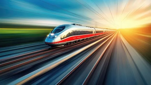
In the demanding world of railway applications, designing printed circuit boards (PCBs) that can withstand harsh conditions like vibration and shock is critical. Railway electronics must operate reliably in environments with constant movement, temperature fluctuations, and mechanical stress. So, how can engineers create PCBs that meet these tough requirements? The answer lies in specialized design techniques, robust materials, and strategic protective measures.
In this comprehensive guide, we'll explore the unique challenges of PCB design for railway applications, focusing on anti-vibration PCB design for railway systems, shock-resistant PCB solutions, and other key strategies like conformal coating for railway PCBs, PCB mounting techniques for railway environments, and railway electronics ruggedization. Whether you're an engineer or a project manager in the railway industry, this blog will provide actionable insights to ensure your electronics perform reliably under pressure.
Understanding the Challenges of PCB Design for Railway Applications
Railway systems operate in some of the harshest environments for electronics. Trains experience constant vibration from tracks, sudden shocks from stops and starts, and exposure to dust, moisture, and extreme temperatures. These conditions can cause PCB components to loosen, crack, or fail if not designed with care. For instance, a study by industry experts indicates that vibration frequencies in railway environments can range from 5 Hz to 200 Hz, with acceleration forces up to 5g during operation. Such forces can lead to mechanical fatigue in solder joints and component leads over time.
Beyond mechanical stress, railway PCBs must comply with strict safety and reliability standards, such as EN 50155, which outlines requirements for electronic equipment used in rolling stock. Meeting these standards means addressing not only vibration and shock but also thermal management, electromagnetic interference (EMI), and fire safety. Let's dive into the specific strategies to overcome these challenges.
Anti-Vibration PCB Design for Railway Systems
One of the primary challenges in railway electronics is managing vibration. Anti-vibration PCB design for railway applications focuses on minimizing the impact of mechanical stress on components and connections. Here are some key techniques:
- Component Placement and Orientation: Position critical components, such as heavy capacitors or connectors, in areas of the PCB with minimal vibration impact. Orient components perpendicular to the direction of dominant vibration to reduce stress on solder joints. For example, if the primary vibration is along the train's direction of travel, align components side-to-side rather than front-to-back.
- Use of Damping Materials: Incorporate vibration-damping materials like silicone pads or rubber mounts between the PCB and its enclosure. These materials absorb energy and reduce the transmission of vibration to the board.
- Board Thickness and Material Selection: Use thicker PCBs (e.g., 2.0 mm or more) made from high-strength materials like FR-4 with enhanced glass transition temperatures (Tg) above 170°C. A thicker board is less likely to flex under vibration, protecting components from mechanical failure.
By implementing these strategies, engineers can significantly extend the lifespan of PCBs in railway applications, ensuring consistent performance even under constant vibration.
Designing Shock-Resistant PCBs for Railway Environments
Shocks in railway systems often occur during sudden stops, starts, or collisions. These high-impact events can dislodge components or damage traces if the PCB isn't designed for resilience. Creating a shock-resistant PCB for railway use involves both design and material considerations:
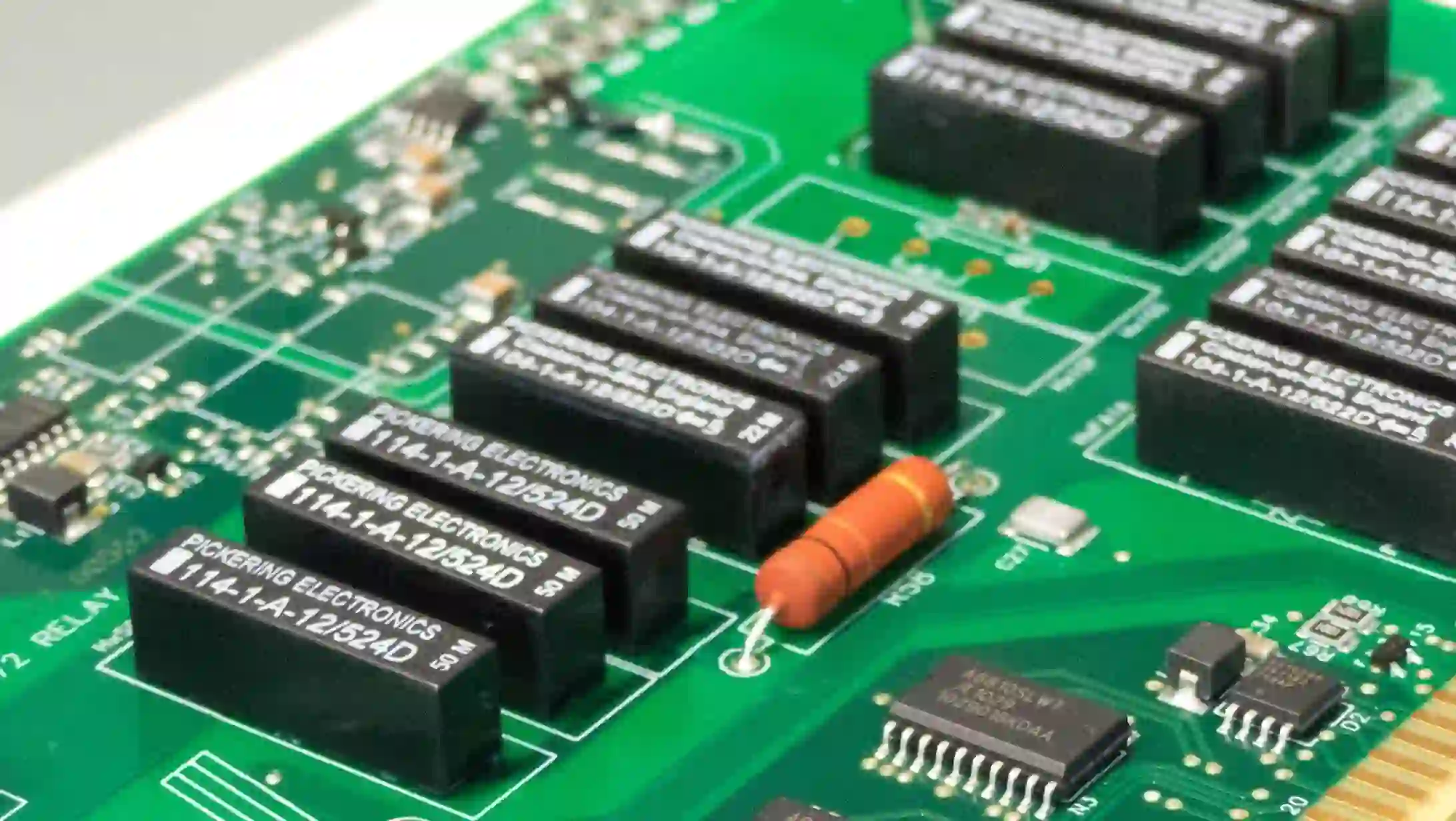
- Secure Component Mounting: Use surface-mount technology (SMT) components with smaller footprints, as they are less likely to detach during shocks compared to through-hole components. Additionally, apply adhesives or underfill materials around critical components to lock them in place.
- Reinforce Solder Joints: Opt for lead-free solder with higher tensile strength to withstand sudden impacts. Ensure proper reflow profiles during manufacturing to avoid weak joints, targeting a shear strength of at least 20 N per joint for critical connections.
- Flexible PCB Layouts: Design the PCB with wider traces (e.g., 0.3 mm or more for power lines) and avoid placing vias near high-stress areas. This reduces the risk of trace cracking during shock events.
Testing for shock resistance is also vital. Standards like EN 61373 specify shock tests with forces up to 50g for short durations (e.g., 30 ms). Simulating these conditions during the design phase can help identify weak points before production.
Conformal Coating for Railway PCBs: Protecting Against Environmental Stress
Railway PCBs are often exposed to dust, moisture, and temperature extremes, which can lead to corrosion or short circuits. Conformal coating for railway PCBs acts as a protective barrier, shielding the board from these environmental factors. Here's how it helps:
- Moisture and Dust Resistance: Coatings like acrylic or silicone create a thin, protective layer (typically 25-75 microns thick) that prevents water ingress and dust accumulation. This is crucial for PCBs in undercarriage control systems or outdoor signaling equipment.
- Vibration and Shock Dampening: Some coatings, such as polyurethane, offer slight flexibility, helping to absorb minor vibrations and reduce stress on components.
- Thermal and Chemical Protection: Conformal coatings can withstand temperature ranges from -40°C to 125°C, common in railway environments, and protect against chemical exposure from cleaning agents or pollutants.
When selecting a coating, consider the application method (e.g., spray, dip, or brush) and ensure compatibility with the PCB's components. For instance, avoid coatings that might interfere with connectors or heat sinks. Proper application and curing processes are essential to achieve uniform coverage without bubbles or gaps.
PCB Mounting Techniques for Railway Applications
How a PCB is mounted within its enclosure can make a significant difference in its ability to withstand vibration and shock. PCB mounting techniques for railway systems focus on secure installation and stress distribution. Consider these approaches:
- Use of Shock-Absorbing Mounts: Install PCBs using rubber or spring-loaded mounts that isolate the board from direct enclosure vibrations. These mounts can reduce transmitted forces by up to 50%, based on typical damping coefficients.
- Strategic Mounting Points: Distribute mounting points evenly across the PCB to avoid stress concentration. For a standard 100 mm x 160 mm board, use at least four mounting points near the corners to minimize flexing.
- Rigid Enclosures: House the PCB in a sturdy metal enclosure that protects against external impacts. Ensure the enclosure is designed to avoid resonance at common railway vibration frequencies (e.g., 10-50 Hz), which could amplify stress on the board.
Additionally, consider using locking fasteners or thread-locking compounds to prevent screws from loosening over time due to vibration. Regular inspection of mounting hardware during maintenance can also prevent long-term failures.
Railway Electronics Ruggedization: Building for Durability
Railway electronics ruggedization goes beyond individual design elements to encompass a holistic approach to durability. This includes not only vibration and shock resistance but also thermal management, EMI shielding, and compliance with industry standards. Here are some core principles:
- Thermal Design: Railway environments often involve wide temperature swings. Use heat sinks or thermal vias to dissipate heat from power components, targeting a junction temperature below 85°C for critical ICs even at ambient temperatures of 70°C.
- EMI Protection: High-speed trains generate significant electromagnetic noise. Incorporate ground planes and shielding layers in the PCB stack-up to reduce interference, aiming for signal integrity with impedance matching at 50 ohms for high-speed lines.
- Compliance with Standards: Adhere to standards like EN 50155 for temperature, humidity, and vibration, as well as EN 45545 for fire safety. Use flame-retardant materials (e.g., UL94 V-0 rated) to minimize risks in case of electrical faults.
Ruggedization also involves rigorous testing. For instance, accelerated life testing (ALT) can simulate years of vibration and thermal cycling in a matter of weeks, helping engineers validate designs before deployment. A typical ALT setup might expose a PCB to 10g vibration at 50 Hz for 100 hours to mimic long-term stress.
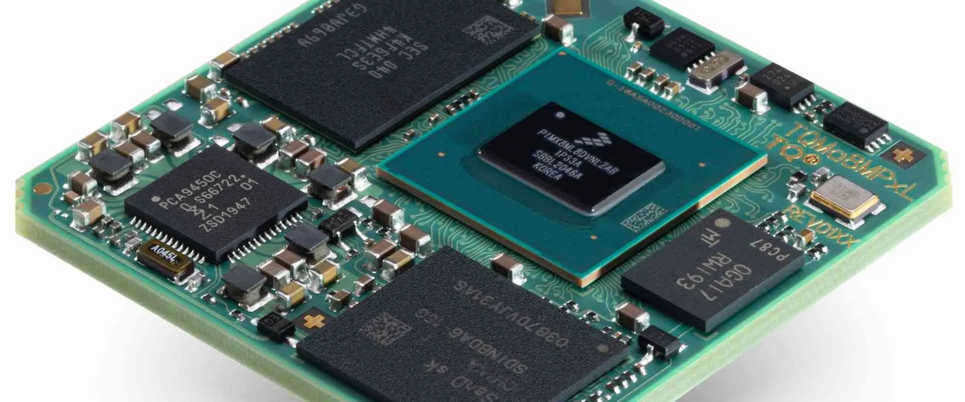
Material Selection: The Foundation of Reliable Railway PCBs
The choice of materials plays a pivotal role in the performance of railway PCBs under vibration and shock. Beyond standard FR-4, consider advanced laminates like polyimide, which offer better thermal stability (Tg up to 250°C) and flexibility for high-stress environments. Copper thickness also matters—opt for at least 2 oz/ft2 for power traces to handle current loads and resist cracking.
For solder masks, select high-durability options that can withstand repeated thermal cycles without peeling. Green or black masks with a thickness of 15-20 microns provide good protection while maintaining visibility for inspection. Finally, ensure that all materials meet RoHS and REACH compliance for environmental safety, as required by railway regulations in many regions.
Testing and Validation for Railway PCB Reliability
Before deployment, railway PCBs must undergo extensive testing to ensure they can handle real-world conditions. Key tests include:
- Vibration Testing: Simulate track conditions using shaker tables to apply forces from 5 Hz to 200 Hz at accelerations up to 5g, per EN 61373 standards.
- Shock Testing: Conduct drop or impact tests to replicate sudden forces, ensuring components remain secure under 50g shocks for 30 ms.
- Environmental Testing: Expose PCBs to temperature cycles (-40°C to 85°C), humidity (up to 95% RH), and salt spray to verify conformal coating effectiveness.
Advanced tools like finite element analysis (FEA) can also predict stress points on the PCB during the design phase, allowing for adjustments before manufacturing. Combining simulation with physical testing ensures the highest reliability.
Conclusion: Building Resilient PCBs for the Future of Railways
Designing PCBs for railway applications requires a deep understanding of the unique challenges posed by vibration, shock, and environmental factors. By focusing on anti-vibration PCB design for railway systems, creating shock-resistant PCBs, applying conformal coating for railway PCBs, using effective PCB mounting techniques, and prioritizing railway electronics ruggedization, engineers can build electronics that stand the test of time.
At ALLPCB, we’re committed to supporting the railway industry with high-quality PCB solutions tailored to these demanding conditions. Whether you need assistance with material selection, design optimization, or testing, our expertise ensures your projects run smoothly—on and off the tracks. With the right strategies and partnerships, you can overcome the toughest challenges and keep railway systems moving forward safely and reliably.


