ALLPCB


< there! Below is the SEO-friendly blog post for ALLPCB titled **"Optimizing Power Integrity in Edge Computing PCBs: Techniques for Low-Power Consumption"**. I've structured it to target the specified long-tail keywords while providing practical, actionable information for engineers and PCB designers. Let's dive right into the content. ```html
Edge computing is transforming industries by bringing data processing closer to the source, but designing PCBs for edge devices comes with unique challenges. One of the biggest hurdles is ensuring power integrity while maintaining low-power consumption. How can you optimize an edge computing PCB power distribution network to achieve this balance? In this blog, we’ll explore proven techniques for low-power PCB design for edge devices, power integrity simulation for edge PCBs, DC-DC converter selection for edge computing, and strategies for minimizing voltage drop in edge PCBs. Let’s break down these concepts and provide actionable insights to help you design efficient and reliable edge computing systems.
Why Power Integrity Matters in Edge Computing PCBs
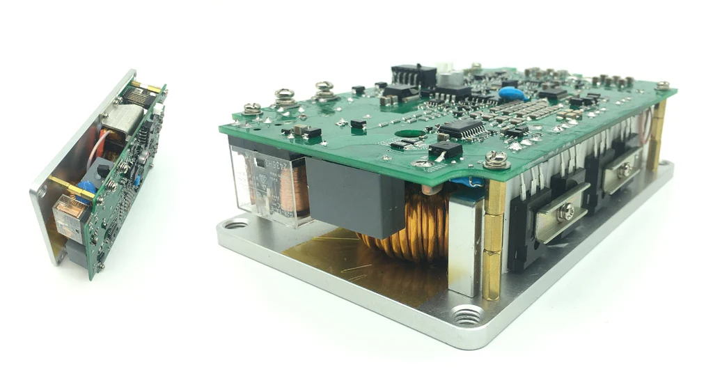
Edge computing devices often operate in remote or resource-constrained environments, making power efficiency and stability critical. These systems need to process data quickly while consuming minimal energy to extend battery life or reduce heat dissipation. Power integrity ensures that the voltage supplied to components remains stable, avoiding noise or fluctuations that can lead to system failures or performance issues. A well-designed edge computing PCB power distribution network is the foundation for achieving this stability.
Without proper power integrity, edge devices may experience issues like signal distortion, data corruption, or even complete system crashes. For instance, a sudden voltage drop can cause a processor to malfunction, leading to incorrect data processing. This is especially problematic in applications like IoT sensors or autonomous vehicles, where reliability is non-negotiable. By focusing on low-power PCB design for edge systems, you can minimize energy waste while ensuring consistent performance.
Key Challenges in Edge Computing PCB Power Distribution Networks
Designing an edge computing PCB power distribution network comes with several challenges due to the unique requirements of these systems. Let’s look at some of the most common issues:
- Limited Space: Edge devices are often compact, leaving little room for complex power delivery systems. This means every component and trace must be optimized for efficiency.
- Low-Power Requirements: Many edge devices run on batteries or limited power sources, demanding designs that minimize energy consumption without sacrificing performance.
- High-Speed Signals: Edge systems often handle high-speed data processing, which can introduce noise into the power network if not managed properly.
- Environmental Factors: Edge devices may operate in harsh conditions, such as extreme temperatures or humidity, which can affect power delivery and component reliability.
Addressing these challenges starts with a robust power distribution network (PDN) that can deliver stable voltage and current to all components while minimizing losses. Let’s dive into specific techniques to achieve this.
Techniques for Low-Power PCB Design for Edge Devices
Creating a low-power PCB design for edge systems requires a combination of careful planning and strategic component selection. Here are some effective techniques to consider:
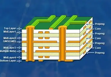
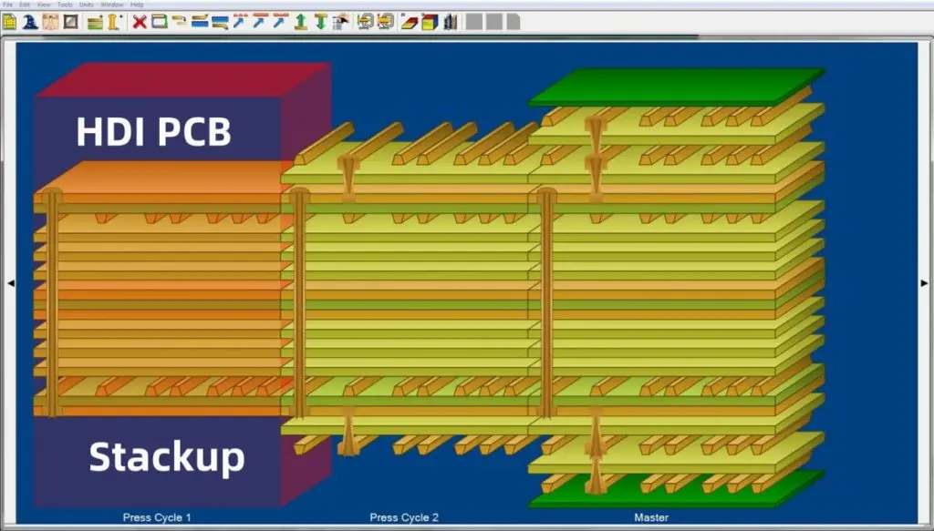
1. Optimize Layer Stackup for Power Efficiency
The layer stackup of your PCB plays a significant role in power distribution and signal integrity. For edge computing PCBs, a well-planned stackup can reduce power losses and noise. Use dedicated power and ground planes to create a low-impedance path for current flow. For example, placing a ground plane directly below a power plane can reduce electromagnetic interference (EMI) by up to 30% in high-speed designs.
Additionally, keep power traces short and wide to minimize resistance. A trace with a width of 20 mils can handle currents up to 1A with minimal voltage drop, compared to a narrower 10-mil trace, which may introduce significant losses.
2. Use Low-Power Components
Selecting components with low power consumption is a fundamental step in low-power PCB design for edge devices. Opt for microcontrollers and sensors with sleep modes or ultra-low-power states. For instance, some modern microcontrollers consume less than 1 μA in sleep mode, extending battery life in edge applications.
Also, consider using energy-harvesting techniques if your device operates in remote locations. Solar or thermal energy harvesting can supplement battery power, reducing overall consumption.
3. Implement Power Gating
Power gating is a technique where unused sections of the PCB are turned off to save energy. In edge computing devices, where certain functions may only activate periodically (like data transmission in IoT sensors), power gating can reduce consumption by up to 50%. Design your circuit to isolate power domains and switch them off when not in use, using transistors or dedicated power management ICs.
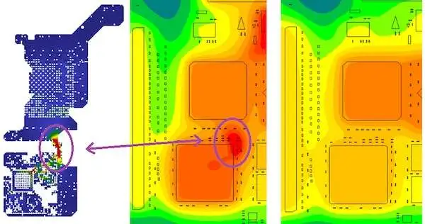
Power Integrity Simulation for Edge PCBs: Why and How
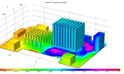
Power integrity simulation for edge PCBs is a critical step in ensuring that your design can handle real-world conditions. Simulation tools allow you to analyze the behavior of your power distribution network before manufacturing, identifying potential issues like voltage drops or noise.
Benefits of Power Integrity Simulation
Simulation helps you verify that your PDN can maintain stable voltage levels across all components, even during peak current demands. For example, a simulation might reveal that a particular trace experiences a 0.2V drop under load, allowing you to adjust the design before it becomes a problem. This proactive approach can save significant time and cost during prototyping.
How to Perform Power Integrity Simulation
Start by modeling your PDN using simulation software that supports DC and AC analysis. Input parameters like trace impedance (typically around 50 mΩ for short traces), capacitor values, and load currents. Run simulations to check for voltage ripple, which should ideally be below 1% of the nominal voltage (e.g., 50 mV for a 5V rail). Adjust your design by adding decoupling capacitors or redistributing power planes if issues are detected.
DC-DC Converter Selection for Edge Computing: Making the Right Choice
Choosing the right DC-DC converter is vital for maintaining power efficiency in edge computing systems. DC-DC converters step down or step up voltage levels to match the needs of different components, and the wrong choice can lead to energy waste or instability.
Factors to Consider in DC-DC Converter Selection
- Efficiency: Look for converters with high efficiency at low loads, as edge devices often operate in idle or low-power modes. A converter with 90% efficiency at 100 mA is ideal for battery-powered systems.
- Output Ripple: Ensure the converter produces minimal output ripple (e.g., less than 20 mV) to avoid introducing noise into the system.
- Size: Edge devices require compact components, so choose a converter with a small footprint, such as a switching regulator in a 3mm x 3mm package.
- Thermal Performance: Select a converter that operates efficiently without overheating, especially for edge devices in harsh environments.
For example, a buck converter with a switching frequency of 2 MHz can provide stable output voltage while minimizing the size of external components like inductors and capacitors. Pair it with low-ESR capacitors to further reduce ripple and improve transient response.
Minimizing Voltage Drop in Edge PCBs: Practical Tips
Voltage drop is a common issue in edge computing PCBs, especially when current must travel long distances across traces or through multiple components. Minimizing voltage drop in edge PCBs ensures that all parts of the system receive the required power without performance degradation.
1. Use Wider and Shorter Traces
As mentioned earlier, wider traces reduce resistance and thus minimize voltage drop. For a current of 2A, a trace width of 30 mils on a 1 oz copper layer can limit the drop to under 50 mV over a 2-inch length. Use PCB design tools to calculate trace resistance based on copper thickness and length for precise results.
2. Place Decoupling Capacitors Strategically
Decoupling capacitors act as local energy reservoirs, supplying current during sudden load changes and reducing voltage fluctuations. Place them as close as possible to high-current components like processors or transceivers. A 10 μF capacitor with a low ESR (e.g., 0.1 Ω) can stabilize voltage within 10 mV during transient events.
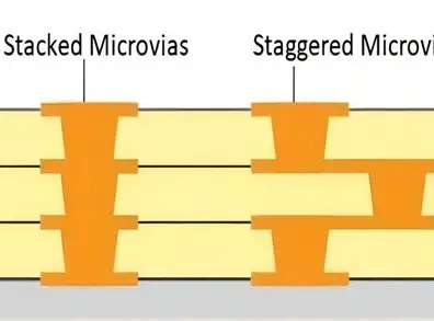
3. Optimize Via Placement
Vias introduce additional resistance and inductance, contributing to voltage drop. Minimize the number of vias in power paths, and use multiple vias in parallel for high-current connections to reduce effective resistance. For instance, using four vias instead of one can cut resistance by 75%.
Best Practices for Power Distribution Network Design in Edge Computing
Here are some overarching best practices to tie together the concepts of power integrity and low-power design in edge computing PCB power distribution networks:
- Plan Early: Incorporate power integrity considerations from the schematic stage, not as an afterthought during layout.
- Test Iteratively: Use simulation and prototyping to validate your design at every stage, adjusting as needed based on real-world performance.
- Balance Cost and Performance: While high-end components can improve efficiency, they may not always be necessary. Focus on cost-effective solutions that meet your specific power and performance needs.
- Stay Updated: Edge computing technology evolves rapidly, so keep abreast of new components, tools, and design techniques that can enhance power integrity.
Conclusion: Building Efficient Edge Computing PCBs with Power Integrity
Optimizing power integrity in edge computing PCBs is not just about meeting technical requirements—it’s about enabling reliable, efficient, and long-lasting systems that can thrive in challenging environments. By focusing on low-power PCB design for edge devices, leveraging power integrity simulation for edge PCBs, making informed DC-DC converter selections for edge computing, and minimizing voltage drop in edge PCBs, you can create designs that excel in performance and efficiency.
Start by building a robust edge computing PCB power distribution network, and use the techniques and tips shared in this blog to guide your process. With careful planning and the right tools, you can overcome the unique challenges of edge computing and deliver systems that power the future of technology.