ALLPCB


In the fast-paced world of automated teller machines (ATMs), performance and reliability are critical. One of the biggest challenges in designing PCBs (printed circuit boards) for ATMs is managing heat effectively. Poor thermal management can lead to system failures, reduced lifespan of components, and costly downtime. So, how can you optimize ATM performance through advanced thermal management techniques for PCBs? This blog dives deep into practical solutions like ATM PCB thermal simulation, heat dissipation PCB design, thermal vias for ATM PCBs, strategic component placement for heat management, and selecting materials with optimal PCB material thermal conductivity.
Whether you're an engineer designing ATM systems or a manufacturer looking to enhance reliability, this guide offers actionable insights to ensure your PCBs handle heat efficiently. Let’s explore these advanced techniques step by step to help you build robust and high-performing ATM systems.
Why Thermal Management Matters for ATM PCBs
ATMs operate in diverse environments, often facing high temperatures, humidity, and continuous usage. The electronic components on an ATM’s PCB, such as processors, power regulators, and communication modules, generate significant heat during operation. If this heat isn’t managed properly, it can cause overheating, leading to malfunctions or permanent damage. Effective thermal management ensures consistent performance, extends the lifespan of components, and reduces maintenance costs.
Beyond reliability, thermal management impacts energy efficiency. Overheated components draw more power, increasing operational costs for ATM operators. By focusing on heat dissipation PCB design and other strategies, you can create systems that run cooler and more efficiently.
Key Challenges in ATM PCB Thermal Management
Before diving into solutions, let’s understand the specific thermal challenges faced by ATM PCBs:
- High Power Density: Modern ATMs pack powerful components into compact spaces, increasing heat generation per square inch.
- Enclosed Environments: ATMs are often housed in tight enclosures with limited airflow, making natural cooling difficult.
- Continuous Operation: Many ATMs run 24/7, leaving little time for components to cool down.
- Environmental Factors: Outdoor ATMs face temperature extremes, from scorching heat to freezing cold, adding stress to thermal systems.
Addressing these challenges requires a combination of design techniques, material choices, and simulation tools. Let’s explore the most effective strategies for optimizing thermal performance in ATM PCBs.
1. Leveraging ATM PCB Thermal Simulation for Better Design
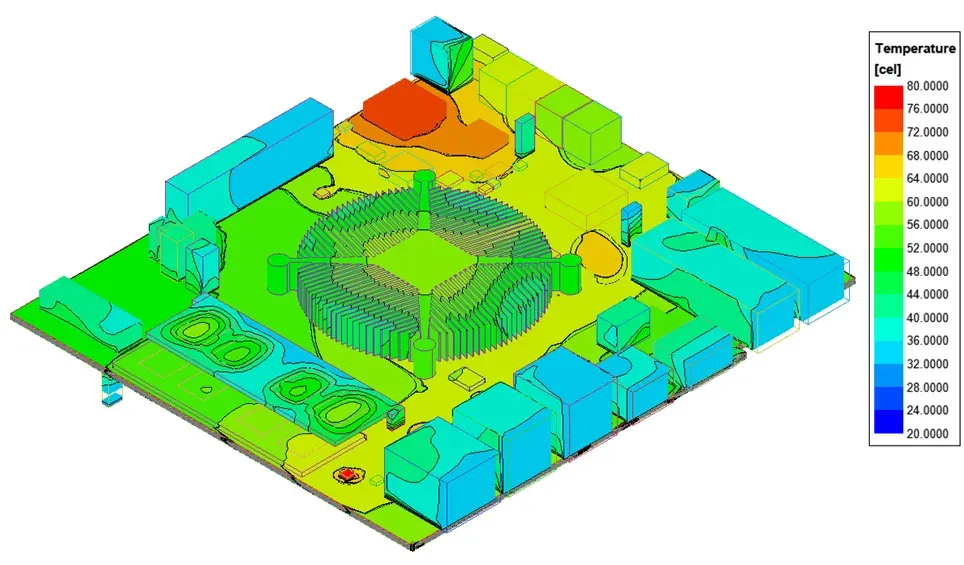
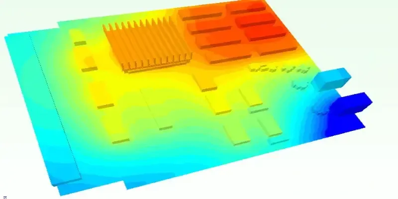
One of the first steps in managing heat is to predict how it will behave in your PCB design. ATM PCB thermal simulation tools allow engineers to model heat flow, identify hotspots, and test different cooling strategies before manufacturing. These simulations use finite element analysis (FEA) to calculate temperature distribution across the board based on component power dissipation, material properties, and environmental conditions.
For example, a simulation might reveal that a high-power processor on your ATM PCB reaches 85°C under load, exceeding its safe operating range of 70°C. With this data, you can adjust the design—perhaps by adding thermal vias or repositioning the component—before building a physical prototype. This saves time and reduces costly redesigns.
Thermal simulation software often integrates with PCB design platforms, allowing seamless analysis during the layout process. By running simulations under worst-case scenarios (e.g., maximum ambient temperature of 40°C and full operational load), you can ensure your ATM PCB withstands real-world conditions.
2. Heat Dissipation PCB Design: Core Principles
Effective heat dissipation PCB design is at the heart of thermal management. The goal is to transfer heat away from critical components and distribute it across the board or into the environment. Here are some core principles to follow:
- Use Copper Planes for Heat Spreading: Copper has excellent thermal conductivity (around 400 W/m·K), making it ideal for dissipating heat. Design your PCB with large copper ground planes to act as heat sinks, spreading thermal energy away from hotspots.
- Increase Board Thickness: Thicker PCBs (e.g., 2.0 mm instead of 1.6 mm) can handle more heat due to increased material mass, though this must be balanced with cost and weight considerations.
- Optimize Trace Widths: Wider traces for high-current paths reduce resistive heating, which can contribute to overall board temperature. For instance, a trace carrying 5A should be at least 2 mm wide to minimize heat buildup.
By incorporating these elements into your heat dissipation PCB design, you create a foundation for better thermal performance in ATM systems.
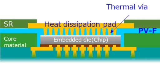
3. Using Thermal Vias in ATM PCBs for Enhanced Cooling
Thermal vias are small holes drilled into the PCB and filled or plated with copper to transfer heat between layers or to a heat sink. For ATM PCBs, thermal vias are especially useful under high-power components like voltage regulators or microcontrollers, where heat buildup is significant.
For instance, placing a 4x4 grid of thermal vias (each 0.3 mm in diameter) beneath a power IC can reduce its operating temperature by 10-15°C, depending on the board’s configuration. The vias conduct heat to a copper plane or external heat sink on the opposite side of the board, improving overall cooling.
When designing thermal vias for ATM PCBs, consider the following:
- Density: More vias mean better heat transfer, but too many can weaken the board’s structure or interfere with signal routing.
- Placement: Position vias directly under or near heat-generating components for maximum effect.
- Connection: Ensure vias connect to large copper areas or heat sinks to dissipate heat effectively.
Thermal vias are a low-cost, high-impact solution for managing heat in compact ATM designs.
4. Strategic Component Placement for Heat Management
Where you place components on an ATM PCB can make a big difference in thermal performance. Poor placement can trap heat or create hotspots, while strategic positioning helps distribute heat evenly. Follow these tips for effective component placement for heat management:
- Separate High-Heat Components: Place high-power components, like processors or power supplies, away from each other to avoid concentrated heat zones. For example, keep a distance of at least 10 mm between two ICs dissipating 2W each to prevent thermal overlap.
- Position Near Cooling Features: Place heat-sensitive components near airflow paths or heat sinks if your ATM design includes active cooling.
- Avoid Enclosed Areas: Don’t cluster components in areas with poor ventilation, as this traps heat and raises temperatures.
By carefully planning component placement, you can minimize thermal stress and improve the reliability of your ATM PCB.
5. Selecting PCB Materials with High Thermal Conductivity
The choice of PCB material plays a huge role in thermal management. Standard FR-4 material, commonly used in PCBs, has a thermal conductivity of about 0.3 W/m·K, which is low for high-power applications like ATMs. To improve heat dissipation, consider materials with higher PCB material thermal conductivity:
- Metal-Core PCBs (MCPCBs): These use a metal base layer (often aluminum) with thermal conductivity up to 200 W/m·K, making them excellent for heat dissipation. They’re ideal for ATM PCBs with high-power components.
- High-Tg FR-4: If cost is a concern, opt for high-Tg (glass transition temperature) FR-4 variants, which handle higher temperatures (up to 170°C) compared to standard FR-4 (130°C).
- Ceramic Substrates: For extreme heat scenarios, ceramic materials like aluminum nitride (170-200 W/m·K) offer superior thermal performance, though at a higher cost.
Choosing the right material depends on your budget, thermal requirements, and environmental conditions. For outdoor ATMs exposed to high temperatures, investing in materials with better thermal conductivity can prevent failures and extend system life.
Additional Thermal Management Techniques for ATM PCBs
Beyond the core strategies above, consider these additional techniques to further enhance thermal performance:
- Heat Sinks and Cooling Fans: Attach heat sinks to high-power components to increase surface area for heat dissipation. For enclosed ATMs, small fans can provide active cooling, reducing temperatures by 20-30% in some cases.
- Thermal Pads and Compounds: Use thermal interface materials (TIMs) between components and heat sinks to improve heat transfer. A thermal pad with conductivity of 5 W/m·K can lower component temperatures significantly.
- Multi-Layer Board Design: Distribute heat across multiple layers by routing power and ground planes strategically. A 6-layer PCB, for instance, offers more space for heat-spreading copper planes than a 2-layer board.
Combining these methods with simulation and design best practices ensures a comprehensive approach to thermal management.
Testing and Validation for Thermal Performance
After designing your ATM PCB with these techniques, testing is crucial to validate thermal performance. Use infrared (IR) cameras to measure temperatures across the board under full load. Compare these results with your ATM PCB thermal simulation data to confirm accuracy. If a component exceeds its maximum operating temperature (e.g., 70°C for a specific IC), revisit the design to add more vias, adjust placement, or enhance cooling.
Additionally, perform long-term stress tests to simulate continuous operation. Running the PCB at full capacity for 48 hours can reveal potential thermal issues that short-term tests might miss. Document all findings to refine future designs.
Conclusion: Building Reliable ATMs with Advanced Thermal Management
Optimizing ATM performance starts with effective thermal management of PCBs. By using ATM PCB thermal simulation, focusing on heat dissipation PCB design, incorporating thermal vias, planning component placement for heat management, and selecting materials with high PCB material thermal conductivity, you can create systems that run cooler, last longer, and perform reliably even in tough conditions.
At ALLPCB, we understand the importance of thermal management in high-stakes applications like ATMs. Our expertise in PCB manufacturing ensures that your designs are built with precision and quality, supporting advanced thermal solutions for maximum performance. Start implementing these techniques in your next project to stay ahead in the world of ATM technology.