 ALLPCB


When designing a printed circuit board (PCB), one of the most critical decisions is selecting the right substrate material. The substrate impacts everything from performance and durability to cost and manufacturability. Whether you're working on a standard design, a high-temperature application, or a flexible circuit, the material you choose must align with your PCB form factor and project needs. In this comprehensive guide, we’ll explore PCB substrate materials, including FR-4 PCB, high-temperature PCB material, flexible PCB material, and PCB dielectric properties, to help you make an informed choice.
Why PCB Substrate Material Matters
The substrate is the foundation of your PCB, providing mechanical support and electrical insulation between conductive layers. It directly affects signal integrity, thermal management, and the board’s ability to withstand environmental stresses. Choosing the wrong material can lead to issues like signal loss, overheating, or mechanical failure. By understanding the properties of different materials, you can match them to your specific form factor—whether it’s a rigid, flexible, or hybrid design—and ensure optimal performance.
Let's dive into the key types of substrate materials and how they cater to various applications and form factors.
Understanding PCB Substrate Materials: The Basics
PCB substrates are typically made from insulating materials that support copper traces and components. The most common materials fall into three broad categories: rigid, flexible, and specialty substrates for extreme conditions. Each material has unique properties like dielectric constant (Dk), dissipation factor (Df), thermal conductivity, and mechanical strength that influence its suitability for different projects.
Key Properties to Consider
Before exploring specific materials, it’s important to understand the properties that define their performance:
- Dielectric Constant (Dk): This measures a material’s ability to store electrical energy. A lower Dk is better for high-frequency applications to minimize signal delay. For example, standard materials have a Dk around 4.0-4.5, while advanced materials can go as low as 2.2.
- Dissipation Factor (Df): This indicates energy loss as heat. A lower Df (e.g., 0.02 or less) is ideal for maintaining signal integrity in high-speed designs.
- Thermal Conductivity: This shows how well a material dissipates heat. High thermal conductivity (e.g., 1.0 W/mK or higher) is crucial for power electronics.
- Coefficient of Thermal Expansion (CTE): This measures how much a material expands with heat. A lower CTE (e.g., 14-17 ppm/°C) helps prevent cracking during temperature changes.
With these properties in mind, let’s look at the most popular substrate materials and their applications.
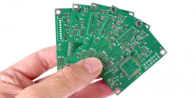
FR-4 PCB: The Industry Standard for Rigid Boards
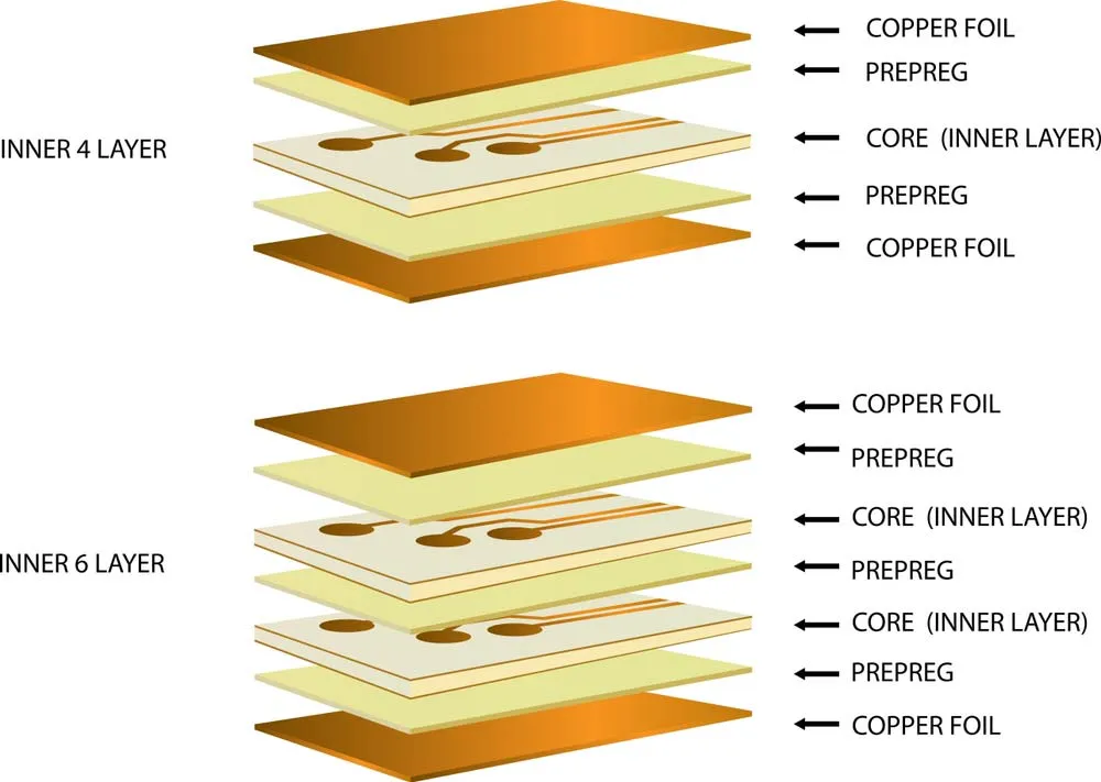
FR-4 PCB is the most widely used substrate material for rigid circuit boards due to its affordability, versatility, and reliable performance. Made from woven fiberglass cloth and epoxy resin, FR-4 (Flame Retardant 4) offers a good balance of electrical, thermal, and mechanical properties.
Properties of FR-4
- Dielectric Constant (Dk): Approximately 4.0-4.5 at 1 MHz, suitable for general-purpose applications.
- Dissipation Factor (Df): Around 0.02, acceptable for low-to-mid frequency designs.
- Thermal Conductivity: Low, about 0.3 W/mK, which can limit use in high-power designs.
- Operating Temperature: Up to 130°C (standard grades), with some variants reaching 150°C.
Applications and Form Factors
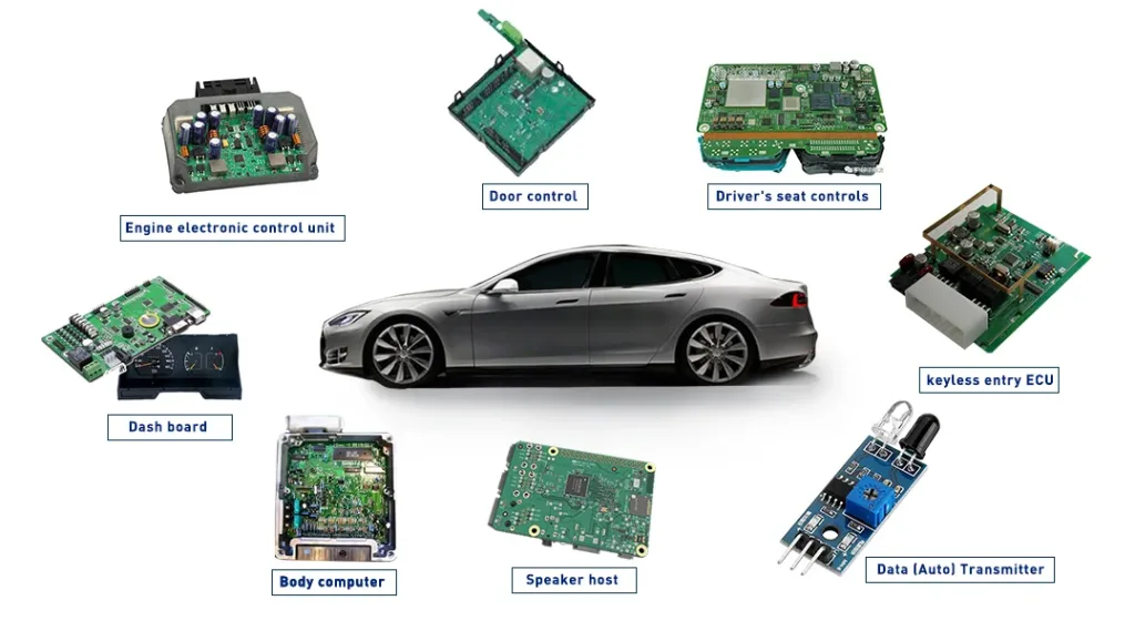
FR-4 is ideal for standard rigid PCBs used in consumer electronics, industrial controls, and automotive systems. Its mechanical strength makes it perfect for multi-layer boards in compact designs. However, it’s not suitable for high-frequency applications above 1 GHz due to signal loss or for extreme thermal environments.
Pros and Cons of FR-4
- Pros: Cost-effective, widely available, good mechanical stability.
- Cons: Limited thermal conductivity and higher dielectric loss at high frequencies.
For most standard projects, FR-4 is a go-to choice. However, if your design involves high heat or flexibility, other materials might be better suited.
High-Temperature PCB Material: Built for Harsh Environments
For applications where heat is a major concern, such as in aerospace, automotive power systems, or LED lighting, high-temperature PCB material is essential. These substrates are designed to withstand temperatures beyond the limits of standard FR-4, often exceeding 150°C or even 200°C.
Common High-Temperature Materials
- High-Tg FR-4: A variant of FR-4 with a higher glass transition temperature (Tg) of 170°C-180°C. It offers better thermal stability while maintaining affordability.
- Polyimide: Known for excellent thermal resistance, withstanding up to 260°C. It has a Dk of around 3.5 and a low Df of 0.008, making it suitable for high-frequency designs as well.
- Ceramic Substrates: Materials like aluminum oxide or aluminum nitride provide exceptional thermal conductivity (up to 170 W/mK) and can handle extreme temperatures, though they are more expensive.
Applications and Form Factors
High-temperature materials are used in rigid PCBs for power electronics, engine control units, and industrial machinery. Their ability to manage heat ensures reliability in environments where standard materials would degrade or fail.
Pros and Cons of High-Temperature Materials
- Pros: Superior heat resistance, improved reliability in harsh conditions.
- Cons: Higher cost, especially for ceramics, and sometimes reduced mechanical flexibility.
If your project involves elevated temperatures or thermal cycling, investing in a high-temperature substrate can prevent long-term failures and extend the lifespan of your PCB.
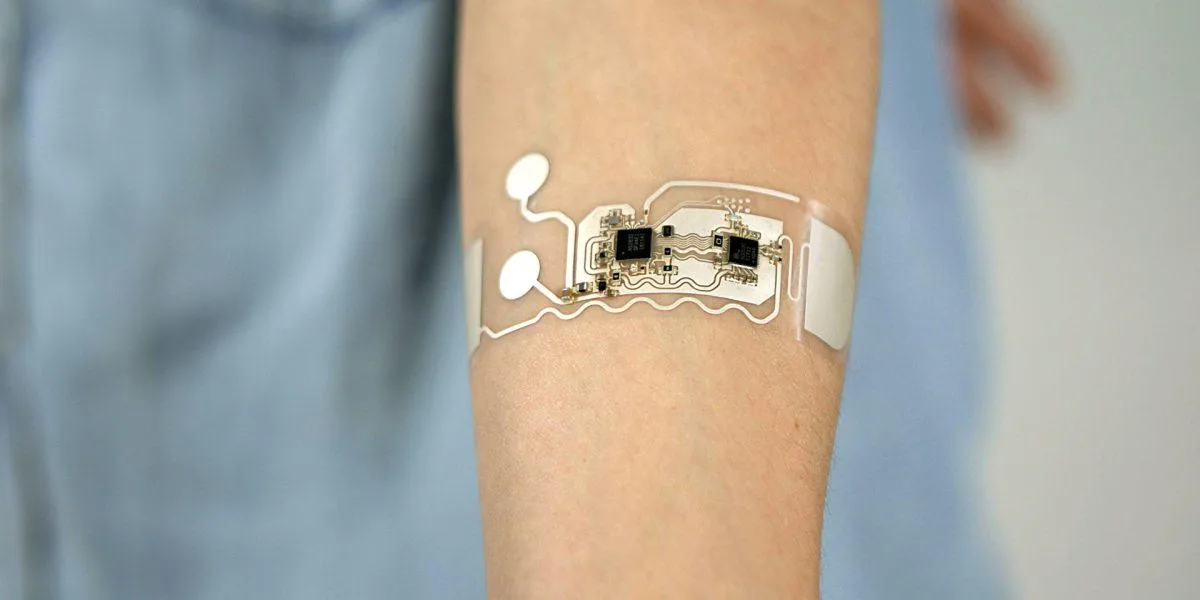
Flexible PCB Material: Adapting to Unique Form Factors
Flexible PCB material is the backbone of flex and rigid-flex circuits, which are essential for compact, lightweight, and dynamic designs. These materials allow PCBs to bend and fold, fitting into tight spaces or moving parts without breaking.
Properties of Flexible Materials
The most common flexible substrate is polyimide, which offers:
- Dielectric Constant (Dk): Around 3.2-3.5, better than FR-4 for high-frequency signals.
- Dissipation Factor (Df): Low, around 0.002-0.008, minimizing signal loss.
- Thermal Resistance: Can withstand up to 260°C, suitable for demanding environments.
- Flexibility: High tensile strength and bendability for dynamic applications.
Applications and Form Factors
Flexible PCBs are widely used in wearable devices, medical equipment, and foldable electronics. They’re perfect for designs where space is limited or where the board must conform to a specific shape. Rigid-flex designs, combining rigid and flexible sections, are popular in smartphones and cameras.
Pros and Cons of Flexible Materials
- Pros: Lightweight, adaptable to unique shapes, reliable in dynamic applications.
- Cons: Higher manufacturing cost, more complex design process.
For projects requiring non-traditional form factors, flexible substrates offer unmatched versatility, though they often come at a premium.
PCB Dielectric Properties: Impact on Performance
PCB dielectric properties are at the heart of how a substrate affects electrical performance. The dielectric constant (Dk) and dissipation factor (Df) determine how signals propagate through the board, especially in high-speed or high-frequency designs.
Why Dielectric Properties Matter
In high-speed circuits, a lower Dk reduces signal propagation delay, which is critical for maintaining timing in applications like 5G or data centers. For instance, a material with a Dk of 3.0 can support faster signal speeds compared to FR-4’s Dk of 4.5. Similarly, a lower Df reduces energy loss, ensuring cleaner signals over long distances.
Choosing Materials Based on Dielectric Needs
- For low-frequency designs (under 1 GHz), standard FR-4 with a Dk of 4.0-4.5 works well.
- For high-frequency designs (above 1 GHz), consider materials like polyimide (Dk ~3.5) or specialty laminates with Dk as low as 2.2.
- For high-speed digital circuits, prioritize low Df materials (below 0.005) to minimize signal distortion.
Understanding dielectric properties ensures your PCB performs as expected, especially in advanced applications where signal integrity is non-negotiable.
How to Choose the Right Substrate for Your PCB Form Factor
Selecting the right substrate involves balancing performance, cost, and manufacturability. Here are key steps to guide your decision:
- Define Your Application: Determine if your project needs a rigid, flexible, or hybrid form factor. Identify operating conditions like temperature, frequency, and mechanical stress.
- Evaluate Electrical Needs: Check signal speed and frequency requirements to choose a material with suitable dielectric properties.
- Consider Thermal Demands: For high-heat environments, opt for high-temperature materials with good thermal conductivity and low CTE.
- Assess Budget Constraints: Balance performance with cost. Standard FR-4 is economical for many projects, while specialty materials may be necessary for niche applications.
- Test and Validate: Prototype your design with the chosen material to ensure it meets performance expectations under real-world conditions.
Conclusion: Make an Informed Choice for Your PCB Design
Choosing the right substrate is a foundational step in PCB design that directly impacts performance, reliability, and cost. Whether you’re using a standard FR-4 PCB for a rigid board, a high-temperature PCB material for harsh conditions, or a flexible PCB material for compact designs, understanding the properties of each material is key. Pay close attention to PCB dielectric properties to ensure signal integrity, especially in high-speed or high-frequency applications.
By carefully evaluating your project’s needs and matching them to the right PCB substrate materials, you can create a design that performs reliably and meets your goals. Take the time to analyze your requirements, and don’t hesitate to consult with experts or test prototypes to confirm your choice. With the right substrate, your PCB will be built to last, no matter the form factor or application.


