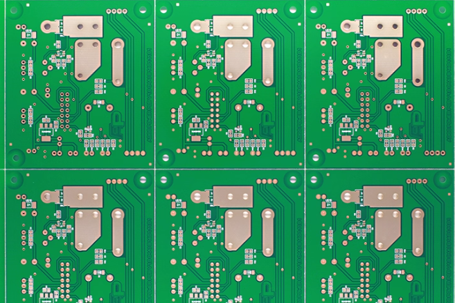
In the fast-evolving world of printed circuit board (PCB) design, line width in mils plays a critical role in determining performance, reliability, and manufacturability. As devices become smaller and more complex, understanding and optimizing line width is essential for engineers working on cutting-edge projects. So, what does the future hold for line width in PCB design? It’s all about precision, shrinking dimensions, and adapting to advanced technologies like HDI PCB, flexible PCB, and 3D PCB. In this blog, we’ll dive deep into the trends and technologies shaping the future of PCB design, focusing on line width and its impact on modern electronics.
What Is Line Width in Mils and Why Does It Matter?
Line width, often measured in mils (1 mil = 0.001 inches), refers to the thickness of the conductive traces on a PCB. These traces carry electrical signals between components, and their width directly affects the board’s performance. A narrower line width can save space and allow for denser designs, but it may also increase resistance and affect signal integrity. Wider traces, on the other hand, can handle more current and reduce resistance but take up more space.
Why does this matter? As electronics shrink in size—think smartphones, wearables, and IoT devices—engineers must balance space constraints with electrical performance. Line width is at the heart of this challenge, influencing impedance, heat dissipation, and manufacturing costs. With emerging technologies pushing the boundaries of PCB design, understanding and optimizing line width is more important than ever.
PCB Design Trends: How Line Width Fits into the Bigger Picture
The future of PCB design is driven by the need for smaller, faster, and more efficient electronics. Line width plays a starring role in these trends. Let’s explore how it connects to some of the most significant developments in the industry, including HDI PCB, flexible PCB, and advanced PCB technology.
1. High-Density Interconnect (HDI) PCB: Pushing Line Width to the Limit
HDI PCB technology is all about packing more functionality into smaller spaces. These boards use microvias, blind vias, and buried vias to create dense, multi-layer designs. To achieve this, line widths often shrink to as little as 3-5 mils, compared to the 6-10 mils common in traditional PCBs. This reduction allows for tighter routing and more components on a single board.
However, working with such narrow traces comes with challenges. For instance, a line width of 3 mils may increase resistance, potentially affecting signal speeds, especially in high-frequency applications like 5G devices where signals can exceed 1 GHz. Engineers must carefully calculate impedance—often aiming for a standard 50 ohms in RF designs—to ensure performance isn’t compromised. Additionally, manufacturing precision becomes critical, as even slight deviations in trace width can lead to signal loss or crosstalk.
The trend in HDI PCB design is clear: line widths will continue to decrease as demand for compact electronics grows. By 2025 and beyond, we expect to see line widths approaching 2 mils or less in cutting-edge applications, driven by advancements in manufacturing techniques like laser drilling for microvias.
2. Flexible PCB: Balancing Line Width with Bendability
Flexible PCBs are revolutionizing industries like wearables and medical devices by allowing boards to bend and conform to unique shapes. Line width in flexible PCB design must strike a balance between electrical performance and mechanical durability. Traces typically range from 5 to 10 mils, but in high-flex areas, wider traces may be used to prevent cracking under stress.
One key consideration is current-carrying capacity. For example, a 5-mil trace on a flexible PCB made of polyimide material might handle up to 0.5 amps, depending on the copper thickness (often 1 oz or 2 oz per square foot). If the design requires more current, engineers might increase the width to 8 mils or more, even if it means sacrificing some flexibility.
The future of flexible PCB technology points toward even thinner materials and finer traces. Innovations in conductive inks and hybrid rigid-flex designs are making it possible to maintain signal integrity with line widths as small as 4 mils, even in dynamic bending applications. This trend will likely accelerate as wearable tech and foldable devices become more mainstream.
3. 3D PCB: Redefining Line Width in Three Dimensions
3D PCB technology takes design beyond the flat, two-dimensional plane by integrating circuits into three-dimensional structures. This approach is often used in compact devices like hearing aids or automotive sensors, where space is at a premium. Line width in 3D PCB design varies depending on the layer and orientation, but it often falls in the 5-8 mil range to accommodate complex routing across multiple planes.
One unique challenge in 3D PCB design is maintaining consistent impedance across non-planar traces. A trace running along a curved surface might experience slight variations in width due to manufacturing limitations, affecting signal integrity at high frequencies (e.g., above 500 MHz). To address this, advanced simulation tools are used to predict and adjust line widths, ensuring stable performance.
As 3D printing and additive manufacturing techniques improve, we anticipate a shift toward even finer line widths in 3D PCB designs. This will enable more intricate geometries without sacrificing electrical performance, opening new possibilities for miniaturized electronics.
Advanced PCB Technology: The Role of Line Width in Innovation
Beyond specific PCB types, broader advancements in technology are shaping how line width is approached in design and manufacturing. These innovations are setting the stage for the future of electronics, and line width is a critical factor in their success.
1. AI and Automation in PCB Design
Artificial intelligence (AI) and automation tools are transforming PCB design by optimizing line widths for specific applications. These tools can analyze factors like signal speed, power requirements, and thermal performance to recommend the ideal trace width—often down to a fraction of a mil. For instance, in a high-speed design operating at 10 Gbps, AI might suggest a 4.5-mil trace to achieve a target impedance of 50 ohms while minimizing crosstalk.
This trend is expected to grow, with AI-driven design platforms becoming standard in the industry by 2025. Engineers will rely on these tools to handle the complexities of ultra-fine line widths, especially in HDI and high-frequency applications.
2. Sustainable Manufacturing Practices
Sustainability is another driving force in PCB design. Narrower line widths reduce material usage, which can lower costs and environmental impact. However, manufacturing ultra-fine traces (below 3 mils) often requires advanced processes like chemical etching or laser patterning, which must be optimized to minimize waste.
The push for greener practices will likely influence line width standards, encouraging designs that balance performance with efficiency. This means engineers will need to consider not just electrical properties but also the environmental footprint of their trace layouts.
3. High-Frequency and High-Speed Applications
As applications like 5G, autonomous vehicles, and data centers demand faster signal speeds, line width becomes even more critical. At frequencies above 1 GHz, even a small variation in trace width can cause significant signal distortion. For example, a 5-mil trace might need to be paired with a specific dielectric material (like FR-4 with a dielectric constant of 4.2) to maintain signal integrity.
The future of high-speed PCB design will likely involve line widths below 3 mils, supported by advanced materials with lower dielectric losses. This will ensure that next-generation devices can handle data rates exceeding 25 Gbps without sacrificing reliability.
Challenges of Shrinking Line Widths in PCB Design
While smaller line widths enable innovation, they also introduce several challenges that engineers must address. Understanding these obstacles is key to navigating the future of PCB design.
First, there’s the issue of manufacturing precision. Producing traces below 3 mils requires state-of-the-art equipment and tight quality control. Any deviation in width or alignment can lead to defects like open circuits or shorts, especially in HDI designs with microvias.
Second, narrower traces have higher resistance, which can cause voltage drops and heat buildup. For a 3-mil trace carrying 1 amp, the temperature rise could exceed 10°C if not properly managed with adequate copper thickness or thermal vias.
Finally, signal integrity becomes harder to maintain as line widths shrink. Crosstalk, electromagnetic interference (EMI), and impedance mismatches are more likely, particularly in high-speed designs. Engineers often use simulation software to model these effects and adjust line widths accordingly.
Practical Tips for Optimizing Line Width in PCB Design
For engineers looking to stay ahead of the curve, here are some actionable tips for working with line widths in modern PCB design:
- Start with Simulation: Use design software to simulate signal behavior and impedance for different line widths. This helps identify the optimal width before manufacturing.
- Consider Manufacturing Limits: Check with your fabrication partner to understand their minimum line width capabilities. For HDI designs, aim for widths above 3 mils unless advanced processes are available.
- Balance Current and Space: Use wider traces (8-10 mils) for power lines to handle higher currents, and narrower traces (4-6 mils) for signal lines to save space.
- Account for Flexibility: In flexible PCB designs, avoid overly narrow traces in high-bend areas to prevent cracking. A width of 6-8 mils is often a safe choice.
- Stay Updated on Trends: Keep an eye on advancements in materials and manufacturing techniques that support finer line widths without compromising performance.
Conclusion: The Future of Line Width in PCB Design
Line width in mils is a cornerstone of PCB design, influencing everything from signal integrity to manufacturing feasibility. As we move into 2025 and beyond, trends like HDI PCB, flexible PCB, and 3D PCB are pushing line widths to new limits, often below 3 mils, to meet the demands of compact, high-performance electronics. At the same time, advanced PCB technology—powered by AI, sustainable practices, and high-speed applications—is redefining how engineers approach trace design.
By understanding the role of line width and staying informed about emerging trends, engineers can create designs that are not only innovative but also reliable and efficient. Whether you’re working on a next-gen wearable or a high-frequency 5G device, mastering line width is the key to unlocking the full potential of modern PCB design.


