ALLPCB


If you're looking to optimize your PCB manufacturing process, understanding mouse bites is key to efficient panelization and depaneling. Mouse bites are small, perforated breakaway tabs used in PCB panelization to hold individual boards together in a panel during production, making separation easy and cost-effective. In this guide, we’ll dive deep into PCB mouse bites design rules, mouse bites hole size, mouse bites spacing, PCB panelization with mouse bites, and how mouse bites compare to V-scores. Whether you're an engineer or a hobbyist, this post will equip you with actionable insights to streamline your PCB production.
What Are Mouse Bites in PCB Design?
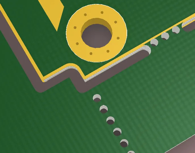
Mouse bites are a popular technique in PCB manufacturing used to facilitate the separation of individual boards from a larger panel. A panel is a single sheet that contains multiple PCB designs, created to save costs and improve efficiency during production. Mouse bites consist of a series of small holes drilled along the edges where the boards connect, forming a perforated line. These perforations weaken the connection, allowing the boards to be snapped apart by hand or with minimal force after assembly.
This method is especially useful for irregularly shaped boards or designs that don’t fit well with other depaneling techniques. By using mouse bites, manufacturers can reduce waste, lower production costs, and ensure a clean separation without damaging the individual PCBs.
Why Use Mouse Bites for PCB Panelization?
Mouse bites offer several advantages in PCB manufacturing, particularly for small to medium production runs or prototype designs. Here are some key benefits:
- Cost-Effective: Mouse bites eliminate the need for expensive depaneling tools or additional routing steps, saving money during production.
- Flexibility: They work well for non-rectangular or complex board shapes that can’t be easily separated using straight-line cuts.
- Minimal Stress: The perforated design reduces mechanical stress on the PCB during separation, minimizing the risk of damage to components or traces near the edges.
- Simplified Process: Mouse bites allow for manual separation without specialized equipment, which is ideal for quick prototyping or low-volume runs.
By incorporating mouse bites into your panelization strategy, you can achieve a balance between efficiency and quality in your PCB production.
PCB Mouse Bites Design Rules: Key Guidelines
Designing mouse bites for your PCB panel requires careful attention to detail to ensure clean separation and avoid damage. Below are some essential design rules to follow when implementing mouse bites in your panelization process.
1. Hole Size for Mouse Bites
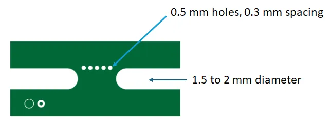
The size of the holes in mouse bites is critical to achieving the right balance between holding the panel together during manufacturing and allowing easy separation afterward. A common hole diameter for mouse bites is between 0.5 mm and 1.0 mm. Smaller holes (around 0.5 mm) provide a stronger connection but may require more force to break apart, while larger holes (around 1.0 mm) make separation easier but might weaken the panel too much during handling.
Most designers opt for a hole size of 0.8 mm as a standard starting point, as it offers a good compromise between strength and ease of depaneling. Always consult with your manufacturing partner to confirm the optimal hole size based on the board material and thickness, which can affect the structural integrity.
2. Mouse Bites Spacing
The spacing between holes, or the distance from the center of one hole to the next, is another crucial factor. Typical spacing ranges from 1.5 mm to 2.5 mm. A spacing of 2.0 mm is often recommended as it provides enough material between holes to maintain panel stability during assembly while still allowing for a clean break.
If the spacing is too tight (e.g., less than 1.5 mm), the panel may become too fragile and break prematurely during production. Conversely, if the spacing is too wide (e.g., over 2.5 mm), separating the boards can become difficult and may result in jagged edges or damage.
3. Number of Holes per Mouse Bite
The number of holes in each mouse bite section depends on the size of the board and the desired strength of the connection. A common practice is to use 3 to 5 holes per mouse bite tab. For smaller boards, 3 holes may suffice, while larger or heavier boards might require 5 holes to ensure stability during handling and assembly.
4. Placement of Mouse Bites
Mouse bites should be placed strategically along the edges of the board to avoid interfering with components, traces, or critical areas. Ideally, place them in areas with at least 2 mm of clearance from any components or sensitive circuitry to prevent damage during separation. Additionally, ensure that mouse bites are evenly distributed along the edges to provide uniform support across the panel.
PCB Panelization with Mouse Bites: Best Practices
Panelization is the process of arranging multiple PCB designs on a single sheet for manufacturing. When using mouse bites for panelization, follow these best practices to maximize efficiency and quality:
- Optimize Board Layout: Arrange boards on the panel to minimize wasted space while ensuring there’s enough room for mouse bites between each board. A gap of 2-3 mm between boards is typically sufficient for placing mouse bite tabs.
- Use Consistent Tab Width: Keep the width of the mouse bite tabs (the material between holes) consistent, usually around 0.5 mm to 1.0 mm, to ensure uniform strength and ease of separation.
- Consider Panel Size: Ensure the overall panel size matches the capabilities of your manufacturing equipment. Most standard panels range from 100 mm x 100 mm to 500 mm x 500 mm, depending on the production setup.
- Account for Board Thickness: Thicker boards (e.g., 2.0 mm or more) may require larger holes or wider spacing to accommodate the increased material strength, while thinner boards (e.g., 0.8 mm) can use smaller holes and tighter spacing.
By adhering to these practices, you can create a panel design that streamlines production and reduces the risk of errors during depaneling.
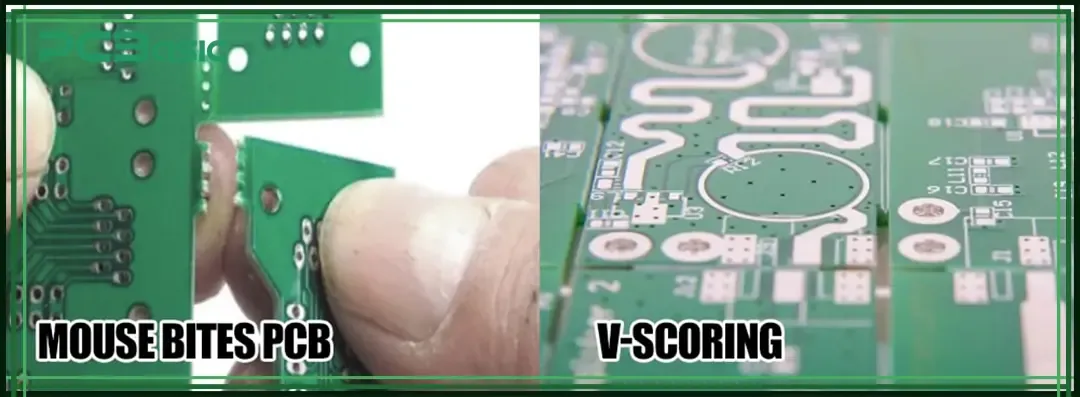
Mouse Bites vs V-Score: Which Depaneling Method Is Right for You?
When it comes to depaneling, mouse bites and V-scores are two of the most common techniques. Each method has its own strengths and weaknesses, so choosing the right one depends on your project’s specific needs. Let’s compare mouse bites vs V-score to help you decide.
What Is a V-Score?
A V-score is a depaneling method where a V-shaped groove is cut into the PCB panel along the separation lines, typically on both the top and bottom surfaces. This groove weakens the material, allowing the boards to be snapped apart along the scored line. V-scoring is often used for rectangular boards and high-volume production runs.
Key Differences Between Mouse Bites and V-Score
- Shape Compatibility: Mouse bites are ideal for irregularly shaped boards or designs with curved edges, as they can be placed anywhere along the board’s perimeter. V-scores, on the other hand, work best for straight-line separations on rectangular boards.
- Cost: Mouse bites are generally more cost-effective for small to medium runs since they don’t require specialized cutting tools beyond standard drilling. V-scoring can be more expensive due to the need for precise grooving equipment, especially for larger panels.
- Edge Finish: Mouse bites often leave small, rough protrusions on the board edges after separation, which may require sanding or additional finishing. V-scores typically result in cleaner, smoother edges with minimal post-processing.
- Stress on Components: Mouse bites distribute stress more evenly during separation, reducing the risk of damage to nearby components. V-scoring can introduce more mechanical stress, especially if the groove is too deep or the board is thin.
- Production Volume: Mouse bites are better suited for prototypes or low to medium volumes due to their simplicity and flexibility. V-scores are often preferred for high-volume production where uniformity and speed are critical.
When to Choose Mouse Bites Over V-Score
Opt for mouse bites if your project involves:
- Irregular or non-rectangular board shapes.
- Small to medium production runs or prototypes.
- Limited budget for depaneling processes.
- Designs where component placement near edges requires minimal separation stress.
Choose V-scores if you’re working on:
- Large-scale production with rectangular boards.
- Projects where a clean, professional edge finish is essential.
- Designs that prioritize speed and uniformity in depaneling.
Common Challenges with Mouse Bites and How to Avoid Them
While mouse bites are a versatile and cost-effective solution, they come with a few potential challenges. Here’s how to address them:
- Rough Edges After Separation: The small tabs left behind after breaking apart mouse bites can create rough edges. To mitigate this, design mouse bites with smaller tabs (around 0.5 mm) or plan for post-separation sanding if aesthetics are a concern.
- Premature Breaking: If the panel is too weak due to overly large holes or tight spacing, it may break during handling. Use a hole size of 0.8 mm and spacing of 2.0 mm as a starting point to ensure stability.
- Component Damage: Placing mouse bites too close to components can risk damage during separation. Maintain at least 2 mm of clearance between mouse bites and any critical areas of the board.
Tips for Implementing Mouse Bites in Your Next PCB Project
To make the most of mouse bites in your PCB panelization, keep these practical tips in mind:
- Collaborate with your manufacturing partner early in the design process to confirm their specific requirements for mouse bite dimensions and panelization.
- Use design software that allows you to easily add mouse bite footprints to your panel layout for precise placement and spacing.
- Test your panel design with a small prototype run to identify any issues with mouse bite strength or separation before scaling up production.
- Document your mouse bite specifications clearly in your design files to avoid miscommunication with the manufacturer.
Conclusion: Streamline Your PCB Production with Mouse Bites
Mastering mouse bites is a valuable skill for any PCB designer or engineer looking to optimize panelization and depaneling processes. By following the PCB mouse bites design rules outlined in this guide—such as selecting the right hole size (0.8 mm), spacing (2.0 mm), and placement—you can ensure efficient production and high-quality results. Whether you’re weighing mouse bites vs V-score or planning PCB panelization with mouse bites, understanding these techniques empowers you to make informed decisions for your projects.
Mouse bites offer a cost-effective, flexible solution for a wide range of PCB designs, especially for prototypes and small to medium runs. With careful planning and attention to detail, you can minimize challenges like rough edges or premature breaking, ensuring a smooth manufacturing process from start to finish. Start incorporating these best practices into your next project to save time, reduce costs, and achieve professional results.