ALLPCB


Advanced Driver Assistance Systems (ADAS) are transforming the automotive industry by enhancing vehicle safety and convenience. At the heart of these systems lie Printed Circuit Boards (PCBs) that control critical functions like lane departure warnings, adaptive cruise control, and automatic emergency braking. However, when ADAS PCBs fail, the consequences can be severe, ranging from system malfunctions to safety risks. In this comprehensive guide, we’ll dive into ADAS PCB failure modes, explore effective PCB troubleshooting techniques, discuss root cause analysis for PCB failures, and provide insights into automotive PCB defect analysis and PCB repair methods. Whether you’re an automotive engineer or a PCB designer, this blog will equip you with practical knowledge to identify, prevent, and resolve common issues.
Why ADAS PCB Reliability Matters in Automotive Applications
ADAS technology relies heavily on the seamless operation of PCBs to process sensor data, execute real-time decisions, and communicate with other vehicle systems. A single failure in an ADAS PCB can disrupt critical safety features, potentially leading to accidents or costly recalls. According to industry studies, over 60% of electronic failures in vehicles are linked to PCB issues, with thermal stress and vibration being primary culprits in automotive environments. Ensuring reliability through proper design, testing, and failure analysis is essential for maintaining safety and performance.

Common ADAS PCB Failure Modes
Understanding the typical ways in which ADAS PCBs fail is the first step in preventing issues. Below, we outline the most common ADAS PCB failure modes seen in automotive applications:
1. Thermal Stress and Overheating
Automotive environments expose PCBs to extreme temperatures, often ranging from -40°C to 85°C. Prolonged exposure to heat can cause solder joint fatigue, delamination of PCB layers, and component degradation. For instance, a microcontroller on an ADAS PCB may fail if its operating temperature exceeds 125°C for extended periods, leading to erratic sensor data processing.
2. Vibration and Mechanical Stress
Vehicles are subject to constant vibration from road conditions and engine operation. This mechanical stress can lead to cracked solder joints, broken traces, or component detachment. Studies indicate that vibration-induced failures account for nearly 20% of PCB issues in automotive systems, especially in high-frequency ADAS applications.
3. Electrical Overstress (EOS)
Electrical overstress occurs when a PCB is exposed to voltage or current beyond its design limits. This can happen due to power surges or improper grounding, damaging sensitive components like capacitors or integrated circuits. For example, a transient voltage spike above 40V on a 12V ADAS system can fry critical chips, halting system functionality.
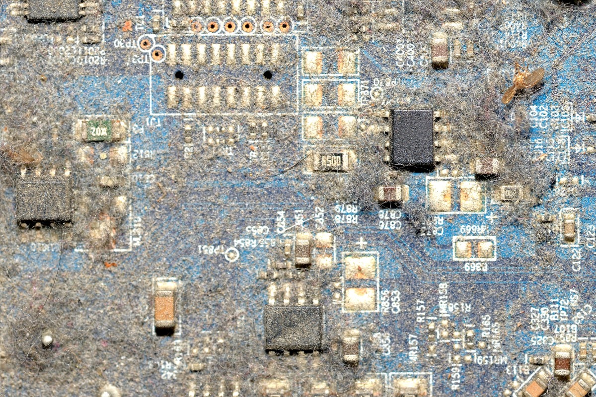
4. Corrosion and Environmental Damage
Moisture, dust, and chemical contaminants in automotive settings can corrode PCB traces and connectors. Over time, corrosion can increase resistance in circuits, leading to signal loss or complete failure. This is particularly problematic for ADAS PCBs mounted near underbody sensors exposed to road salt and water.
5. Manufacturing Defects
Defects introduced during PCB fabrication or assembly, such as poor soldering, misaligned components, or insufficient via plating, can cause intermittent or permanent failures. A poorly soldered joint with a resistance of over 10 milliohms can disrupt signal integrity, affecting ADAS performance.
PCB Troubleshooting Techniques for ADAS Systems
Identifying the root cause of a failure is critical for effective repair and prevention. Here are proven PCB troubleshooting techniques tailored for ADAS applications:
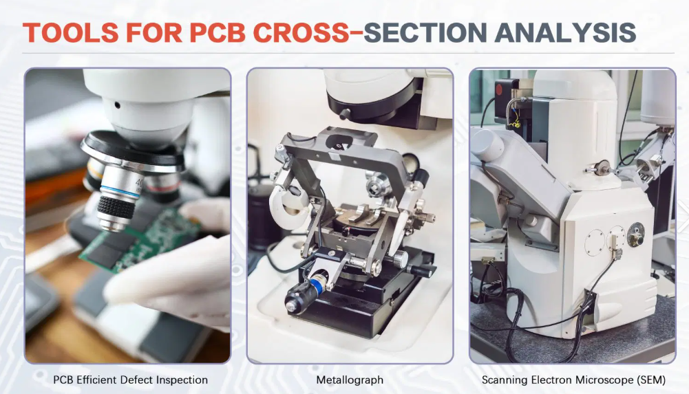
1. Visual Inspection
Start with a thorough visual check using a magnifying glass or microscope. Look for obvious signs of damage like burnt components, cracked solder joints, or corroded traces. A visual inspection can reveal up to 30% of PCB issues without the need for advanced tools.
2. Multimeter Testing for Continuity and Voltage
Use a digital multimeter to test for continuity in traces and measure voltage levels at key points. For instance, if a power rail on an ADAS PCB shows a voltage drop below 3.3V when it should be 5V, there may be a short circuit or failed regulator. This method helps isolate electrical faults quickly.
3. Thermal Imaging for Hotspots
Thermal cameras can detect overheating components or areas of high resistance on a PCB. If a specific IC on an ADAS board shows a temperature of 90°C while surrounding areas are at 50°C, it could indicate a failing component or poor heat dissipation design.
4. Signal Integrity Analysis
Use an oscilloscope to analyze signal integrity, especially for high-speed data lines in ADAS systems. Look for noise, jitter, or signal delays that could affect sensor communication. A signal with a rise time exceeding 5 nanoseconds on a critical line may point to impedance mismatch or trace damage.
5. Functional Testing
Perform functional tests by simulating real-world conditions. Connect the ADAS PCB to a test rig mimicking vehicle sensor inputs and check for correct outputs. If the system fails to respond to a simulated obstacle detection at 50 km/h, the issue could lie in the processing circuitry or firmware.

Root Cause Analysis for PCB Failures in ADAS
Once a failure is identified, conducting a root cause analysis for PCB failures ensures that the underlying issue is addressed. Here’s a step-by-step approach:
1. Data Collection
Gather detailed information about the failure, including environmental conditions, operating parameters, and failure symptoms. For example, note if the ADAS PCB failed after prolonged exposure to 80°C cabin temperatures during a heatwave.
2. Failure Mode Identification
Pinpoint the specific failure mode using the troubleshooting techniques mentioned above. Was it a solder joint crack due to vibration or a burnt capacitor from electrical overstress? Accurate identification narrows down potential causes.
3. Environmental and Operational Analysis
Analyze the conditions under which the PCB operates. High humidity levels above 85% or frequent thermal cycling between -20°C and 60°C can weaken materials over time, leading to failures like delamination.
4. Design and Manufacturing Review
Examine the PCB design for potential flaws, such as inadequate trace width for current loads or insufficient thermal vias for heat dissipation. Also, review manufacturing records for errors like improper soldering temperatures above 260°C during reflow.
5. Implement Corrective Actions
Based on the root cause, update design guidelines, improve manufacturing processes, or enhance environmental protection. For instance, adding conformal coating can protect against corrosion in humid conditions.
Automotive PCB Defect Analysis: Best Practices
Effective automotive PCB defect analysis requires a systematic approach to detect and categorize defects. Here are best practices for ADAS systems:
1. Automated Optical Inspection (AOI)
Use AOI systems during manufacturing to detect surface-level defects like misaligned components or solder bridges. AOI can achieve defect detection rates of up to 95% for visible issues, ensuring quality before deployment.
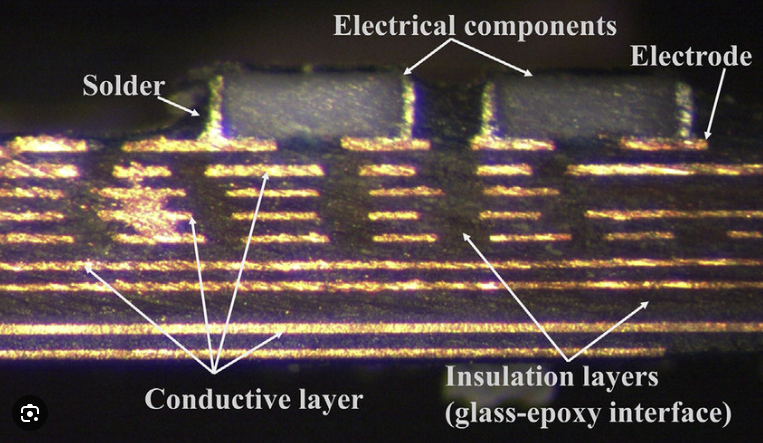
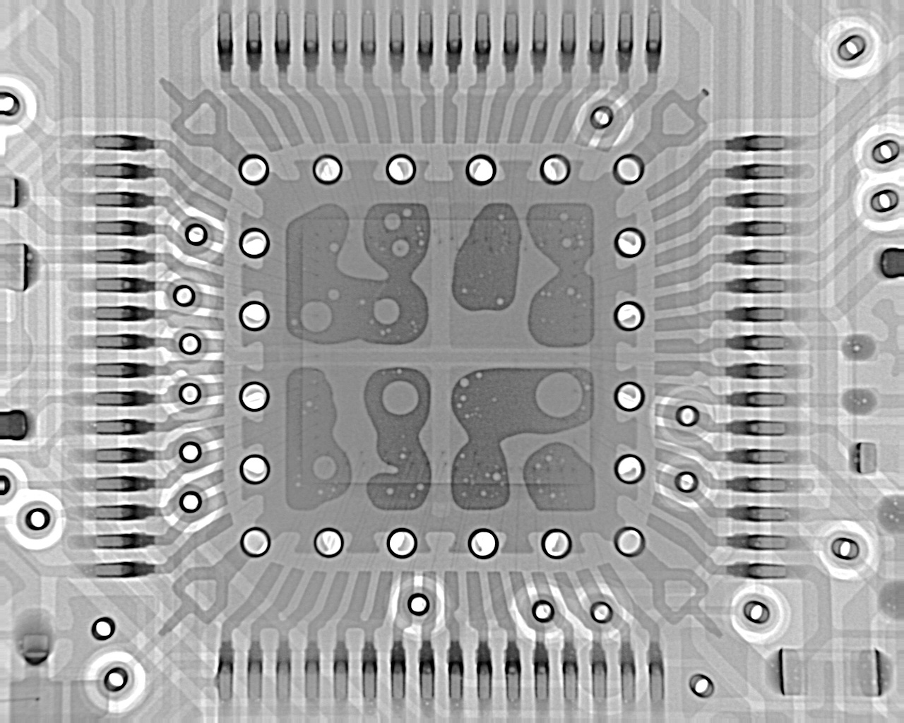
2. X-Ray Inspection for Hidden Defects
For defects beneath components or within multilayer boards, X-ray inspection reveals issues like voiding in solder joints or internal trace breaks. This is critical for ball grid array (BGA) components commonly used in ADAS PCBs.
3. In-Circuit Testing (ICT)
ICT checks for electrical functionality by testing individual components and connections on the PCB. It can identify open circuits or incorrect component values, ensuring that the board meets design specifications.
4. Environmental Stress Testing
Subject ADAS PCBs to accelerated stress tests, such as thermal cycling between -40°C and 125°C or vibration at 10G, to uncover latent defects. This simulates years of real-world use in just days, identifying weak points before field deployment.
PCB Repair Methods for ADAS Systems
Repairing a failed ADAS PCB can be more cost-effective than replacement, provided the damage is localized. Here are practical PCB repair methods for common issues:
1. Solder Joint Repair
For cracked or broken solder joints, carefully remove old solder using a desoldering tool and re-solder the joint with a temperature-controlled soldering iron at around 300°C. Ensure the joint is clean and free of flux residue to prevent future failures.
2. Trace Repair
If a trace is damaged, use conductive epoxy or a small jumper wire to bridge the gap. For high-current traces, ensure the repair material can handle loads up to 2A without overheating.
3. Component Replacement
Replace failed components like capacitors or resistors by desoldering the damaged part and installing a new one with matching specifications. Verify the replacement with a multimeter to ensure correct operation.
4. Conformal Coating Reapplication
After repairs, apply a new layer of conformal coating to protect against moisture and contaminants. Use a silicone-based coating for flexibility in vibrating automotive environments.
5. Post-Repair Testing
After any repair, conduct functional and signal integrity tests to confirm the PCB operates within design parameters. For instance, ensure signal delays remain below 3 nanoseconds on critical ADAS data lines.
Preventing ADAS PCB Failures: Proactive Strategies
While troubleshooting and repair are essential, preventing failures through robust design and manufacturing is even better. Here are proactive strategies to enhance ADAS PCB reliability:
- Design for Environment: Use thermal simulation tools to design PCBs with adequate heat dissipation, ensuring no component exceeds 100°C under load.
- Material Selection: Opt for high-Tg (glass transition temperature) materials like FR-4 with a Tg of 170°C to withstand automotive temperature extremes.
- Robust Testing: Implement rigorous testing protocols, including Highly Accelerated Life Testing (HALT), to identify design weaknesses early.
- Quality Manufacturing: Partner with trusted PCB fabrication and assembly services to minimize manufacturing defects through strict quality controls.
- Protective Measures: Use enclosures and coatings to shield PCBs from moisture, dust, and vibration in harsh automotive environments.
Conclusion: Building Reliable ADAS PCBs for Safer Roads
ADAS PCBs are the backbone of modern vehicle safety systems, and their reliability is non-negotiable. By understanding common ADAS PCB failure modes, applying effective PCB troubleshooting techniques, conducting thorough root cause analysis for PCB failures, performing detailed automotive PCB defect analysis, and mastering PCB repair methods, engineers can ensure these critical components perform flawlessly. Prevention through robust design and testing remains the best defense against failures, paving the way for safer, smarter vehicles. At ALLPCB, we’re committed to supporting the automotive industry with high-quality PCB solutions tailored for demanding applications like ADAS. Let’s build reliability into every layer of your next project.