ALLPCB


In the world of modern electronics, designing circuit boards that balance strength and adaptability is key to innovation. An 8-layer PCB combined with flex PCB technology offers a powerful solution, merging the robustness of rigid multilayer boards with the versatility of flexible circuits. This combination, often referred to as rigid-flex design, is ideal for compact, high-performance devices in industries like aerospace, medical, and consumer electronics. In this blog, we'll explore the essentials of 8-layer PCB rigid-flex design, integration techniques, dynamic bending considerations, material selection, and connector design to help you create efficient and reliable electronic systems.
Whether you're an engineer tackling a complex project or a designer looking for practical insights, this guide will walk you through the critical aspects of combining 8-layer PCBs with flex circuits. Let’s dive into the details of optimizing your designs for performance and durability.
What Is an 8-Layer PCB and Flex PCB Combination?
An 8 layer PCB is a multilayer rigid board with eight conductive layers, typically used for high-density and high-speed applications. These layers allow for complex routing, improved signal integrity, and efficient power distribution. When integrated with flex PCBs—thin, bendable circuits made from materials like polyimide—this design becomes a rigid-flex PCB. The rigid sections provide structural support and house dense components, while the flex sections enable bending and folding to fit into tight spaces or accommodate dynamic movement.
This hybrid approach is perfect for devices where space is limited, and reliability under stress is crucial. Think of wearable devices, drones, or medical implants where the board must conform to unique shapes or endure repeated bending. By leveraging 8-layer PCB rigid-flex design, you can achieve both complexity and adaptability in a single board.

Benefits of 8-Layer PCB Rigid-Flex Design
Combining an 8-layer PCB with flex technology offers several advantages for advanced electronic designs. Here are the key benefits:
- Space Efficiency: The flexible sections allow the board to fold or bend, reducing the overall footprint. This is critical for compact devices where every millimeter counts.
- Enhanced Reliability: Rigid-flex designs reduce the need for connectors and cables between rigid boards, minimizing points of failure and improving durability.
- Signal Integrity: With eight layers, you can dedicate specific layers to ground and power planes, reducing noise and ensuring stable high-speed signals (often exceeding 1 GHz in modern applications).
- Dynamic Applications: The flex portions support repeated bending, ideal for applications like hinges in foldable devices or moving parts in robotics.
These benefits make 8-layer PCB rigid-flex designs a go-to choice for engineers working on cutting-edge technology. However, achieving these advantages requires careful planning and execution, which we’ll cover in the following sections.
Key Considerations for 8-Layer PCB Flex PCB Integration
Integrating flex PCBs with an 8-layer rigid board is a complex process that demands attention to detail. Successful 8-layer PCB flex PCB integration hinges on aligning the rigid and flexible sections seamlessly. Here are the critical factors to consider:
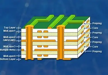
1. Stackup Design
The stackup, or layer arrangement, is the foundation of a rigid-flex PCB. In an 8-layer design, you typically have multiple rigid layers bonded to flexible layers. For instance, you might allocate four layers to the rigid section for power, ground, and high-speed signals, while the flex section uses two to four layers for simpler connections. The transition zone between rigid and flex areas must be carefully designed to avoid stress points that could lead to cracking or delamination.
Tip: Use simulation tools to model signal impedance across layers. Aim for controlled impedance values (e.g., 50 ohms for single-ended traces) to maintain signal integrity in high-speed designs.
2. Bonding Materials
The adhesive or bonding material between rigid and flex layers plays a big role in the board’s reliability. Adhesive-less laminates are often preferred for their superior flexibility and thermal stability, especially in dynamic applications. These materials reduce the risk of separation during bending or thermal cycling.
3. Transition Zones
The area where rigid meets flex is a common failure point if not designed properly. Avoid placing vias or components in this zone, as they can create stress concentrations. Instead, use gradual transitions and reinforce the area with additional coverlay or stiffeners if needed.

Designing for Dynamic Bending in 8-Layer PCBs
Dynamic bending is a defining feature of flex PCBs, but it introduces unique challenges in an 8-layer PCB rigid-flex design. When a board must bend repeatedly—such as in a foldable device or a robotic joint—durability becomes a top priority. Here’s how to optimize for 8-layer PCB dynamic bending:
1. Bend Radius
The bend radius, or the minimum curvature a flex section can handle without damage, is critical. A general rule of thumb is to maintain a bend radius of at least 10 times the thickness of the flex material. For a typical flex layer thickness of 0.05 mm, this means a minimum bend radius of 0.5 mm. Tighter bends increase stress and risk cracking copper traces.
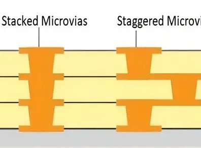
2. Trace Layout
Traces in the flex area should run perpendicular to the bend axis to minimize strain. Avoid sharp corners in trace routing; instead, use curved or teardrop shapes to distribute stress evenly. Additionally, stagger traces across multiple layers to prevent overlap, which can lead to fatigue over time.
3. Reinforcement
For areas under high mechanical stress, consider adding stiffeners—thin rigid materials bonded to the flex section. Stiffeners provide support without sacrificing flexibility elsewhere. They’re especially useful near connectors or mounting points.
Material Selection for 8-Layer PCB Flex Designs
Choosing the right materials is essential for balancing rigidity, flexibility, and performance in 8-layer PCB flex material selection. Here are the primary considerations:
1. Base Materials
For the flex portion, polyimide is the most common material due to its excellent thermal stability (up to 260°C) and flexibility. It can withstand thousands of bend cycles without degrading. For the rigid section, FR-4 is a standard choice for its strength and cost-effectiveness, though high-frequency designs may require low-loss materials like Rogers laminates for better signal performance.
2. Copper Thickness
In flex areas, use thinner copper (e.g., 0.5 oz or 18 μm) to reduce stiffness and improve bendability. In rigid areas, thicker copper (e.g., 1 oz or 35 μm) supports higher current capacity and structural integrity. Balance these choices based on your design’s electrical and mechanical needs.
3. Coverlay and Adhesives
Coverlay, a protective layer over flex traces, should be made of polyimide to match the base material’s properties. When adhesives are necessary, opt for low-flow or no-flow prepregs to prevent excess material from interfering with bending.
Tip: Always consult material datasheets for specific properties like dielectric constant (Dk) and dissipation factor (Df). For high-speed signals, aim for materials with Dk below 3.5 to minimize signal loss.

Suggested Reading: 8-Layer PCB Stackup: Choosing the Right Materials for Your Application
Connector Design for 8-Layer PCB Rigid-Flex Boards
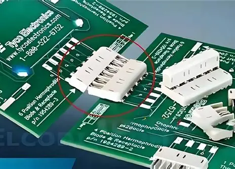
Connectors are a critical but often overlooked aspect of 8-layer PCB connector design in rigid-flex systems. Poor connector placement or selection can lead to mechanical stress or signal degradation. Here’s how to get it right:
1. Connector Placement
Place connectors on rigid sections whenever possible to avoid stress from bending. If a connector must be on a flex area, use a stiffener to reinforce the mounting point and prevent trace damage during mating and unmating cycles.
2. Connector Type
For high-density 8-layer designs, consider zero-insertion-force (ZIF) connectors for flex-to-board connections. ZIF connectors reduce wear on the flex material and provide reliable contact for fine-pitch traces. Surface-mount connectors are also a good choice for rigid areas, as they save space and support high-speed signals.
3. Strain Relief
Incorporate strain relief features near connectors to prevent flex areas from tearing under mechanical load. This can be as simple as adding extra coverlay or designing a gradual curve in the flex section leading to the connector.
Tip: Test connector performance under dynamic conditions. For example, ensure signal integrity at frequencies up to 5 GHz if your design involves high-speed data transfer.
Best Practices for Manufacturing 8-Layer Rigid-Flex PCBs
Manufacturing an 8-layer rigid-flex PCB requires precision to ensure the design translates into a functional product. Here are some best practices to follow:
- Collaborate Early: Work closely with your PCB manufacturer during the design phase to align on material availability, stackup constraints, and bending requirements.
- DFM Guidelines: Adhere to design-for-manufacturability (DFM) rules, such as maintaining minimum trace widths (e.g., 4 mils for flex areas) and avoiding tight tolerances that increase costs.
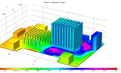
- Prototyping: Build and test prototypes to validate bending performance and signal integrity before full-scale production. Use environmental testing to simulate real-world conditions like temperature cycles from -40°C to 85°C.
By focusing on these practices, you can avoid costly redesigns and ensure your 8-layer PCB rigid-flex design performs as intended.
Common Challenges and How to Overcome Them
Designing and manufacturing 8-layer rigid-flex PCBs isn’t without challenges. Here are some common issues and solutions:
- Delamination: This occurs when rigid and flex layers separate due to thermal or mechanical stress. Use compatible materials with similar coefficients of thermal expansion (CTE) to minimize this risk.
- Signal Loss: High-speed signals can degrade in flex areas due to material properties. Select low-loss materials and keep flex traces short for critical signals.
- Cost: Rigid-flex designs are more expensive than standard PCBs. Optimize your layer count and material choices to balance performance and budget.
Conclusion: Unlocking the Potential of 8-Layer PCB and Flex Integration
Combining an 8-layer PCB with flex technology opens up a world of possibilities for compact, reliable, and high-performance electronic designs. By mastering 8-layer PCB rigid-flex design, integration techniques, dynamic bending considerations, material selection, and connector design, you can create boards that meet the demands of modern applications. From wearable tech to aerospace systems, the ability to blend rigidity and flexibility empowers engineers to push boundaries.
Remember to prioritize careful planning, material compatibility, and collaboration with manufacturing partners to bring your designs to life. With these strategies in hand, you’re well-equipped to tackle the challenges and reap the rewards of 8-layer PCB flex PCB integration.