 ALLPCB


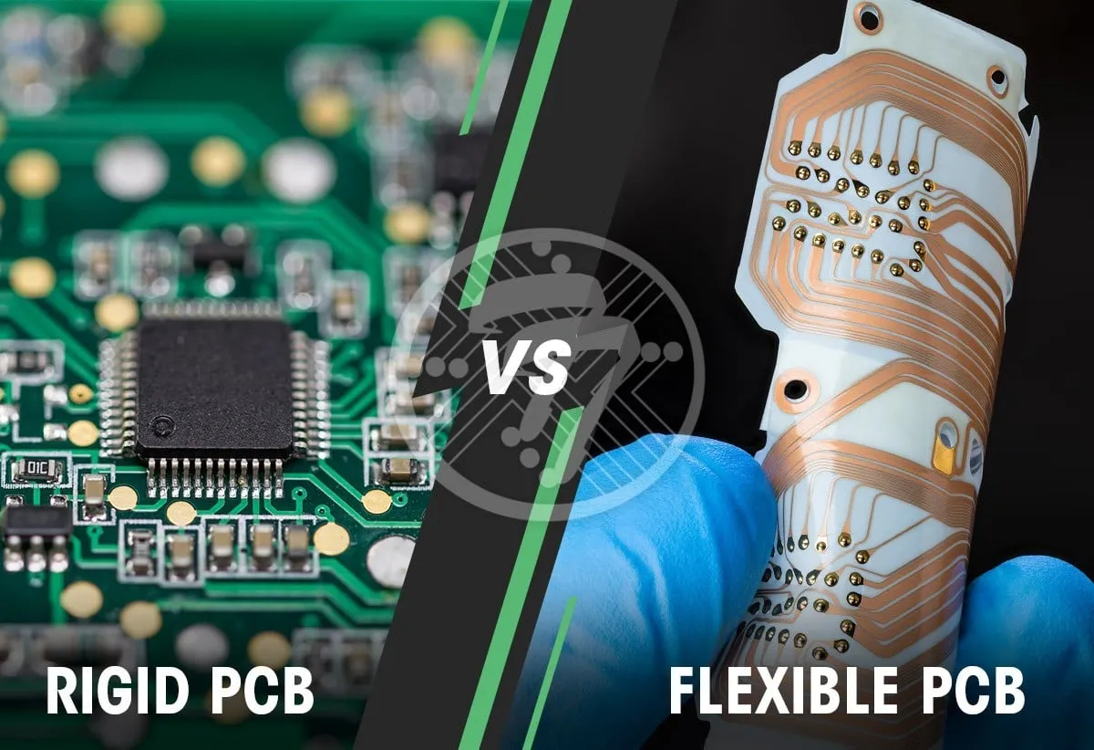
Choosing between rigid and flexible PCBs for your project can be a game-changer. So, which is the right fit? In short, rigid PCBs are ideal for sturdy, cost-effective designs in stable environments, while flexible PCBs shine in compact, dynamic applications where bending and space-saving are key. If you need a hybrid solution, rigid-flex PCBs combine the best of both worlds. In this detailed guide, we’ll dive into the advantages of rigid and flexible PCBs, compare rigid-flex options, and offer a PCB application guide to help you make an informed decision for your next project.
Introduction to PCB Form Factors: Why Choose the Right One?
Printed Circuit Boards (PCBs) are the backbone of modern electronics, connecting components and ensuring devices function as intended. However, not all PCBs are created equal. The form factor—whether rigid, flexible, or a hybrid—plays a huge role in performance, cost, and suitability for specific applications. Selecting the right PCB type can save you time, money, and headaches down the line.
In this blog, we’ll break down the key differences between rigid and flexible PCBs, explore the benefits of each, and provide insights into rigid-flex options. We’ll also cover PCB material selection tips to match your project’s needs. Whether you’re designing for consumer electronics, automotive systems, or medical devices, this guide will help you choose the best PCB type.
What Are Rigid PCBs? Understanding the Basics
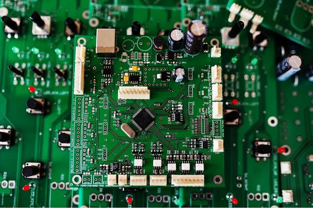
Rigid PCBs are the most common type of circuit board, made from solid, non-flexible materials like fiberglass (FR4). These boards provide a stable platform for mounting components and are widely used in devices where durability and structural integrity are critical.
Rigid PCB Advantages
Rigid PCBs come with several benefits that make them a go-to choice for many projects:
- Cost-Effective: Rigid PCBs are generally cheaper to manufacture than flexible or hybrid options due to simpler production processes and widely available materials. For high-volume production, costs can be as low as $1–$5 per board, depending on complexity.
- Durability: Their solid construction makes them resistant to physical stress, ideal for applications where the board won’t be moved or bent frequently.
- High Component Density: Rigid boards support multiple layers (up to 30 or more in advanced designs), allowing for complex circuits in devices like computers and industrial equipment.
- Thermal Stability: Materials like FR4 can handle temperatures up to 130°C without deforming, making them suitable for high-power applications.
- Ease of Assembly: Their flat, stable surface simplifies automated assembly processes, reducing manufacturing errors.
Rigid PCBs are best for stationary applications where space isn’t a major constraint, such as desktop computers, power supplies, and large industrial systems.
What Are Flexible PCBs? A Closer Look
Flexible PCBs, or flex circuits, are made from thin, bendable materials like polyimide. These boards can conform to unique shapes and fit into tight spaces, making them perfect for modern, compact devices.
Flexible PCB Advantages
Flexible PCBs offer unique benefits that set them apart from their rigid counterparts:
- Space-Saving Design: Flex circuits can bend and fold, reducing the overall size of the device. This is crucial for wearables, smartphones, and other compact electronics where every millimeter counts.
- Lightweight: Made from thinner materials, flexible PCBs weigh less—sometimes as little as 10% of a comparable rigid board—making them ideal for portable devices.
- Dynamic Flexibility: These boards can withstand repeated bending (up to 200,000 cycles in some designs), perfect for applications like foldable displays or moving parts in robotics.
- Reduced Wiring: Flex circuits often integrate connections that would otherwise require separate cables, cutting down on assembly time and potential failure points.
- Thermal and Vibration Resistance: Polyimide materials can endure temperatures up to 200°C and absorb vibrations better than rigid boards, enhancing reliability in harsh environments.
Flexible PCBs are the top choice for applications requiring movement or tight packaging, such as medical implants, automotive sensors, and consumer wearables.
Rigid-Flex PCB Comparison: The Best of Both Worlds
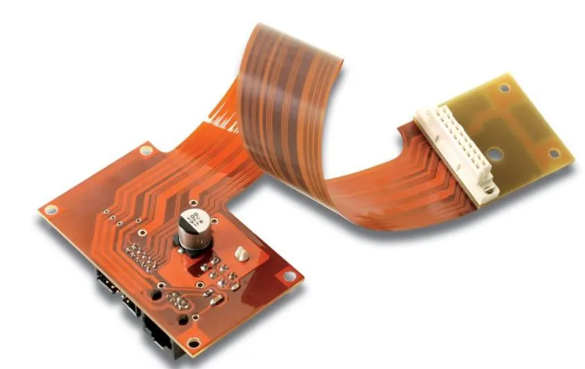
Rigid-flex PCBs combine rigid and flexible sections into a single board, offering the stability of rigid boards with the adaptability of flex circuits. This hybrid design is increasingly popular in complex, high-reliability applications.
Key Benefits of Rigid-Flex PCBs
Rigid-flex boards bring unique advantages to the table:
- Space Efficiency: By integrating rigid and flexible areas, these boards eliminate the need for bulky connectors, saving up to 60% of space compared to separate rigid and flex assemblies.
- Enhanced Reliability: Fewer connectors mean fewer points of failure, improving signal integrity (with impedance control often within ±10%) and overall durability.
- Versatile Applications: Rigid-flex designs support 3D configurations, allowing engineers to fold and twist the board to fit intricate device shapes, as seen in aerospace and medical equipment.
- Cost Savings in Assembly: Combining rigid and flex sections into one board reduces assembly steps, cutting labor costs by up to 30% in some cases.
Challenges to Consider
While rigid-flex PCBs are powerful, they come with challenges. They are more expensive to design and manufacture, often costing 2–3 times more than standard rigid boards due to complex layering and material requirements. Additionally, designing in 3D space requires advanced software and expertise to manage bend radii (typically a minimum of 10x the board thickness) and ensure signal integrity.
Rigid-flex PCBs are ideal for high-density, compact applications where reliability is critical, such as military hardware, advanced wearables, and satellite systems.
PCB Material Selection: Matching Materials to Your Needs
Choosing the right material is just as important as selecting the PCB type. The material impacts performance, cost, and durability. Here’s a quick guide to help with PCB material selection:
Common Materials for Rigid PCBs
- FR4: The standard choice for rigid boards, offering a good balance of cost and performance. It has a dielectric constant of around 4.5 and supports frequencies up to 2 GHz, suitable for most consumer electronics.
- High-Tg FR4: With a glass transition temperature (Tg) of 170–180°C, this variant is better for high-heat applications like automotive electronics.
- Metal-Core: Used in high-power designs like LED lighting, metal-core PCBs (often aluminum) offer excellent thermal conductivity, dissipating heat at rates up to 8 W/mK.
Common Materials for Flexible PCBs
- Polyimide (PI): The go-to material for flex circuits, with a tensile strength of 165 MPa and the ability to withstand temperatures up to 260°C during soldering.
- Polyester (PET): A cheaper alternative to polyimide, though less heat-resistant (up to 105°C). It’s often used in low-cost, less demanding applications.
Considerations for Rigid-Flex PCBs
For rigid-flex designs, materials must balance flexibility and rigidity. Typically, polyimide is used for flex areas, while FR4 forms the rigid sections. Adhesives or no-flow prepregs are critical to bond layers without compromising bendability. Ensure the material stack-up supports your signal speed requirements—high-frequency designs may need low-loss materials with dielectric constants below 3.5.
PCB Application Guide: Choosing the Right Form Factor
Different projects demand different PCB types. Here’s a practical PCB application guide to help you decide:
When to Use Rigid PCBs
- Consumer Electronics: Devices like TVs, desktop PCs, and home appliances rely on rigid PCBs for their stability and cost-effectiveness.
- Industrial Equipment: Machinery with high-power components benefits from the thermal stability and layer capacity of rigid boards.
- Prototyping: Rigid PCBs are easier and cheaper to prototype for initial designs before moving to complex form factors.
When to Use Flexible PCBs
- Wearable Technology: Smartwatches and fitness trackers need lightweight, bendable boards to fit curved designs.
- Automotive Sensors: Flex circuits handle vibrations and tight spaces in vehicle systems, such as dashboard controls.
- Medical Devices: Implants and diagnostic tools often use flex PCBs for their biocompatibility and compact form.
When to Use Rigid-Flex PCBs
- Aerospace and Defense: High-reliability systems like satellites and drones use rigid-flex for 3D configurations and durability under extreme conditions.
- Advanced Consumer Devices: Smartphones and foldable gadgets often incorporate rigid-flex boards to save space and improve performance.
- Robotics: Systems with moving parts benefit from the hybrid design, combining stability for control circuits with flexibility for joints.
Consider your project’s environment, budget, and space constraints. For instance, if your device operates in temperatures above 150°C or requires signal speeds exceeding 5 GHz, consult with your PCB manufacturer to ensure material and design compatibility.
Design Tips for Optimal PCB Performance
Regardless of the form factor, good design practices can make or break your PCB’s success. Here are some actionable tips:
- Plan Layer Stack-Up Early: For multilayer rigid or rigid-flex designs, define your stack-up to manage impedance (target 50 ohms for most high-speed signals) and minimize crosstalk.
- Minimize Bend Stress in Flex Designs: Keep bend radii at least 10 times the board thickness in flexible areas to prevent cracking. Avoid placing vias in bend zones.
- Optimize Trace Widths: Use trace width calculators to match current-carrying capacity. For example, a 1 oz copper layer typically handles 1 A with a 10-mil trace width at room temperature.
- Account for Thermal Management: Add thermal vias or heat sinks in high-power rigid designs to keep temperatures below material limits.
- Test Signal Integrity: Simulate high-speed signals (above 1 GHz) to ensure minimal loss, especially in rigid-flex transitions where impedance mismatches can occur.
Conclusion: Making the Right Choice for Your Project
Deciding between rigid, flexible, or rigid-flex PCBs comes down to your project’s specific needs. Rigid PCBs offer affordability and durability for stable, high-density designs. Flexible PCBs excel in compact, dynamic applications where bending and lightweight construction are priorities. Rigid-flex PCBs provide a powerful hybrid solution for complex, space-constrained, and high-reliability systems, though at a higher cost.
By understanding the advantages of each type, considering PCB material selection, and following a tailored PCB application guide, you can confidently choose the right form factor. Take into account factors like environmental conditions, budget, and design complexity to ensure your PCB performs flawlessly in its intended application.
At ALLPCB, we’re committed to supporting your journey from concept to completion. Whether you’re working on a simple prototype or a cutting-edge device, our expertise and resources are here to help you succeed with the perfect PCB solution.


