ALLPCB


If you're dealing with a malfunctioning single-sided PCB and need a reliable fix, you've come to the right place. This comprehensive guide offers a step-by-step approach to identifying and resolving common issues with single-sided printed circuit boards. Whether you're a beginner or a seasoned technician, our expert solutions will help you tackle problems like broken traces, soldering defects, and component failures. Dive into this detailed single-sided PCB troubleshooting guide to learn practical tips for single-sided PCB repair, address frequent single-sided PCB problems, and master the art of fixing single-sided PCBs.
What Are Single-Sided PCBs and Why Do They Matter?
Single-sided PCBs, also known as single-layer PCBs, are the simplest type of printed circuit boards. They have conductive traces on only one side of the board, with components mounted on the same side. These boards are widely used in basic electronics like calculators, LED lighting, and power supplies due to their cost-effectiveness and ease of manufacturing.
Despite their simplicity, single-sided PCBs can encounter a range of issues that affect their performance. Understanding how to troubleshoot and repair these boards is crucial for maintaining the functionality of electronic devices. In this blog, we'll walk you through the most common problems and provide actionable solutions to get your board back in working order.
Common Issues with Single-Sided PCBs
Single-sided PCBs are prone to specific problems due to their design and usage. Below, we’ve outlined the most frequent issues you might encounter while working with these boards.
1. Broken or Damaged Traces
Traces are the copper pathways on a PCB that connect components. On single-sided PCBs, these traces are exposed on one side, making them vulnerable to physical damage. Scratches, cuts, or corrosion can break the connection, leading to circuit failure.
Signs of the Issue: Intermittent or complete loss of functionality in the affected circuit, visible cracks or gaps in the copper traces.
2. Soldering Defects
Poor soldering is a leading cause of failure in single-sided PCBs. Issues like cold solder joints (where the solder doesn’t properly bond to the component or pad) or solder bridges (unintended connections between pads) can disrupt the circuit.
Signs of the Issue: Loose components, unreliable connections, or short circuits causing unexpected behavior in the device.
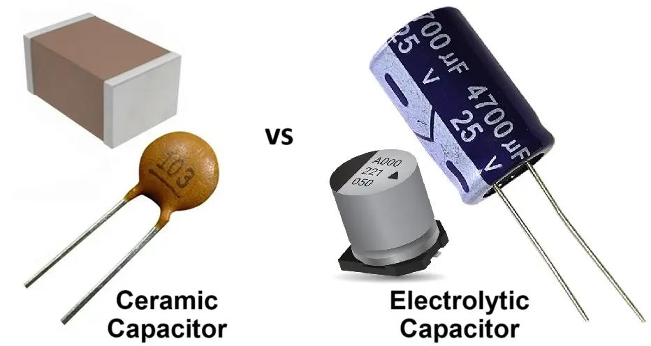
3. Component Failure
Components on a single-sided PCB, such as resistors, capacitors, or diodes, can fail due to overheating, electrical surges, or manufacturing defects. Since components are mounted on one side, identifying a failed part can sometimes be straightforward, but it still requires careful inspection.
Signs of the Issue: Burn marks, bulging capacitors, or a specific part of the circuit not functioning as expected.
4. Overheating and Thermal Stress
Single-sided PCBs often lack the advanced heat dissipation features of multi-layer boards. Prolonged exposure to high temperatures can cause thermal stress, leading to warped boards or damaged components.
Signs of the Issue: Discoloration of the board material, cracked solder joints, or components failing after extended use.
5. Poor Design or Layout Issues
Sometimes, the root cause of a problem lies in the initial design of the PCB. Inadequate spacing between traces, improper component placement, or insufficient trace width can lead to electrical interference or short circuits.
Signs of the Issue: Recurring failures in specific areas of the board, noise or signal interference in the circuit.
Step-by-Step Single-Sided PCB Troubleshooting Guide
Now that you’re familiar with common single-sided PCB problems, let’s dive into a structured approach for troubleshooting. Follow these steps to systematically identify and resolve issues with your board.
Step 1: Visual Inspection
Start by carefully examining the PCB under good lighting. Use a magnifying glass or a microscope if necessary to spot tiny cracks, corrosion, or burn marks. Look for:
- Broken or scratched traces.
- Loose or damaged components.
- Discoloration or signs of overheating.
This initial inspection often reveals obvious issues like a cracked trace or a bulging capacitor, saving you time before moving to more complex testing.
Step 2: Test for Continuity
Use a multimeter set to continuity mode to check if the traces and connections are intact. Place the probes on either end of a trace or between a component lead and its pad. A beep indicates a good connection, while silence suggests a break.
- For broken traces, note the location of the discontinuity for repair.
- For solder joints, test between the component lead and the trace to confirm proper bonding.
Step 3: Check Power Supply and Voltage Levels
Measure the voltage at key points on the board using a multimeter to ensure the power supply is delivering the correct voltage. For example, if a circuit is designed to operate at 5V, a reading of 3.2V could indicate a problem with the power source or a voltage regulator on the board.
- Compare measured values against the circuit’s specifications.
- Look for components like diodes or regulators that might be failing to maintain proper voltage.
Step 4: Test Individual Components
If the issue isn’t with the traces or power supply, test individual components. Use a multimeter to check resistors for correct resistance values (e.g., a 1kΩ resistor should read close to 1000 ohms) and capacitors for continuity or leakage. Replace any components that don’t meet their specified values.
Step 5: Look for Thermal Issues
Use a thermal camera or touch test (carefully!) to identify hot spots on the board. Overheating components or areas with poor heat dissipation might indicate a design flaw or failing part. For instance, a power transistor dissipating 2W of heat without a proper heat sink could reach temperatures above 100°C, risking failure.
Expert Solutions for Fixing Single-Sided PCBs
Once you’ve identified the problem, it’s time to apply the right fix. Below are expert solutions tailored to the common issues discussed earlier in this single-sided PCB repair guide.
Solution 1: Repairing Broken Traces
For a broken trace, you can use a conductive pen or jumper wire to restore the connection:
- Conductive Pen: Clean the area around the break with isopropyl alcohol, then draw over the gap with a conductive ink pen. Allow it to dry for 10-15 minutes before testing continuity.
- Jumper Wire: If the gap is too large, solder a thin insulated wire between the two ends of the broken trace. Secure the wire with adhesive to prevent movement.
Solution 2: Fixing Soldering Defects
For cold solder joints, reheat the joint with a soldering iron at around 300°C and apply fresh solder to ensure a strong bond. For solder bridges, use a desoldering wick or pump to remove excess solder and separate the unintended connection.
Solution 3: Replacing Failed Components
Desolder the faulty component using a desoldering tool or wick, then clean the pads with alcohol. Install a replacement component with matching specifications (e.g., a 10μF capacitor with a 16V rating) and solder it in place. Double-check polarity for components like capacitors and diodes to avoid further issues.
Solution 4: Addressing Overheating
If overheating is a problem, improve heat dissipation by adding a small heat sink to high-power components or increasing airflow around the board. For long-term solutions, consider redesigning the PCB with wider traces (e.g., increasing trace width from 0.2mm to 0.5mm for high-current paths) to reduce resistance and heat buildup.
Solution 5: Correcting Design Flaws
For recurring issues due to poor layout, consult with a PCB design expert to revise the board. Simple changes like increasing trace spacing to 0.3mm or more can prevent electrical interference, while rerouting high-speed signals (e.g., signals at 50MHz) away from sensitive areas can reduce noise.
Tips for Preventing Single-Sided PCB Problems
Prevention is always better than repair. Here are some practical tips to minimize issues with single-sided PCBs:
- Use Quality Materials: Opt for high-quality board substrates and components to reduce the risk of failure.
- Protect the Board: Apply a conformal coating to shield traces from moisture and corrosion, especially in humid environments.
- Avoid Overloading: Ensure the circuit operates within its designed current and voltage limits (e.g., don’t exceed a 1A rating on a trace designed for 0.5A).
- Regular Maintenance: Periodically inspect and clean the board to remove dust or debris that could cause shorts or overheating.
When to Seek Professional Help
While many single-sided PCB issues can be fixed with basic tools and skills, some problems require advanced expertise or equipment. If you encounter persistent failures, complex multi-component issues, or suspect a fundamental design flaw, consider consulting a professional PCB repair service or redesign specialist. They can use advanced diagnostic tools like oscilloscopes to analyze signal integrity (e.g., detecting signal delays of 2ns or more) and provide a long-term solution.
Conclusion
Troubleshooting and repairing single-sided PCBs doesn’t have to be daunting. By following this detailed single-sided PCB troubleshooting guide, you can identify common single-sided PCB problems like broken traces, soldering defects, and component failures, and apply proven solutions for single-sided PCB repair. Whether you’re a hobbyist or a professional, mastering the art of fixing single-sided PCBs will save you time, money, and frustration.
Remember to start with a thorough visual inspection, use the right tools like a multimeter for testing, and apply precise fixes tailored to the issue. With the tips and techniques shared in this blog, you’re well-equipped to handle most challenges that come your way. Keep your boards in top shape, and ensure your electronic projects run smoothly!